Download
1 / 33
330 likes | 475 Views
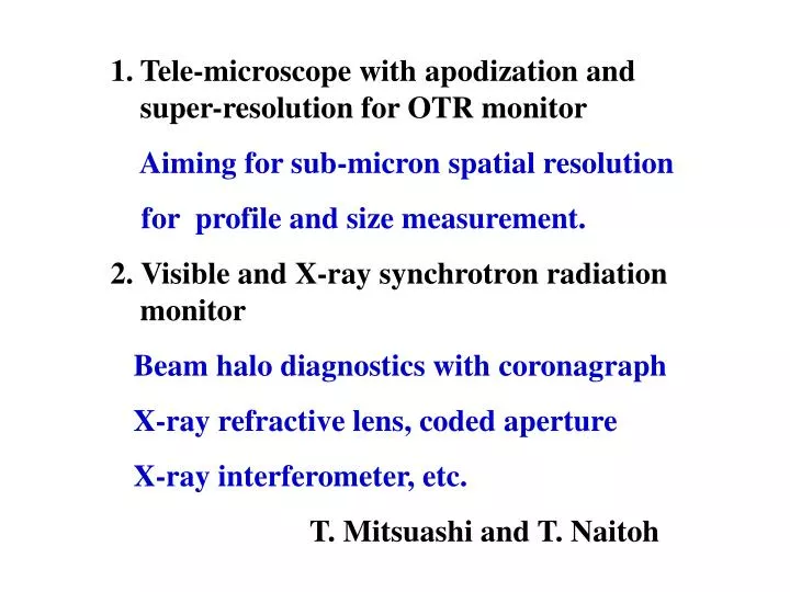
Tele-microscope with apodization and super-resolution for OTR monitor Aiming for sub-micron spatial resolution for profile and size measurement. 2. Visible and X-ray synchrotron radiation monitor Beam halo diagnostics with coronagraph X-ray refractive lens, coded aperture

E N D
Tele-microscope with apodization and super-resolution for OTR monitor • Aiming for sub-micron spatial resolution • for profile and size measurement. • 2. Visible and X-ray synchrotron radiation monitor • Beam halo diagnostics with coronagraph • X-ray refractive lens, coded aperture • X-ray interferometer, etc. • T. Mitsuashi and T. Naitoh
Tele-microscope with apodization* and super-resolution for OTR monitor • *Apodization means modifying phase (by phase shifter) and amplitude (by neutral density filter) transmittance of pupil.
Arrangement of tele-microscope for OTR Reflective Objective Beam Shifter Magnifier CCD Z - polarizer 100mm 100mm 285mm 200 - 400mm 300mm Long working distance 300mm Enough space for OTR target layout perpendicular to electron beam axis.
Analysis of optical performance Points are ; 1. Radial polarization in OTR 2. Sharp intensity distribution of OTR 3. Super-resolution by zonal aperture
Radial polarization of TR • Undulater transition radiation at he PF Observation of UTR through a linear polarization filter. Circles with arrow indicate direction of polarization filter.
(a) (b) Fig. 5 (a) Result of PSF using the OTR as an incident. (b) Detail of PSF near the center. 1. Radial polarization property of OTR makes double peak in the cross section of PSF. 2. Sharp intensity distribution (1/g) makes width of PSF wider.
Phase apodization by radial polarization converter Radial polarization quasi-linear polarization (a) (b) (a)PSF with phase apodization, and detail of central peak (b).
Radial polarization converter Z-polarizer by 8-sector phase plate: this filter converts linear polarization into quasi-radial polarization or oppositely, radial polarization into quasi-linear polarization.
2. Sharp intensity distribution of OTR The PSF with both the phase apodization and the amplitude apodization Amplitude apodization: applying a filter which convert the intensity distribution in the pupil into quasi-uniform distribution.
3.Super resolution by zonal aperture Zonal aperture Optical layout of tele-objective a a1
Cross section of PSF by objective magnification: x2.5 s=1.8mm Resolution 0.72mm Super resolution effect by second mirror reduces rms width of PSF from 0.76mm to 0.72mm.
Location Upstream of QF21X The place where we plan to install the OTR monitor. Q-magnet in this photo is QF21X.
Schedule A f200mm mirrors :already manufactured and waiting the optical testing. The radial polarization converter are not prepared yet. We plan following steps to realize this monitor. Step 1. Design and manufacture a mounting of mirrors, and other optical components until October FY2009. Step 2. Optical tasting of Objective and with other optical component until December 2009. Step 3. Design and manufacture OTR target and extraction system until end of FY2009. Step 4. Study with beam.
1. Visible SRM Aiming for beam halo (coronagraph), temporal structure (streak camera, intensity interferometer, etc.) Other diagnostics etc.
Anti - reflection disk Field lens Relay lens Objective lens Mask (Lyot stop) Opaque disk Opaque disk blocks glare of central image Baffle plates to reduce reflection . . The coronagraph
Image of beam profile without the opaque disk. Image of beam halo with the opaque disk. Observation of beam halo at the Photon Factory
Beam halo observed at different ring currents. • (a)-(e) are observed with single-bunch operation, and (f) is observed with multi-bunch operation. (a) 65.8mA (b) 61.4mA (c) 54.3mA (f) 396.8mA Multi-bunch bunch current 1.42mA (d) 45.5mA (e)35.5mA
Observation for the more out side Single bunch 65.8mA Intensity in here : 2.05x10⁻⁴ of peak intensity 2.55x10⁻⁶ Halo in deep outside Background leavel : about 6x10⁻⁷
Background in classical coronagraph Re-diffraction intensity on the Lyot stop
This leakage of the light can make background level 10-8 (depends on Lyot stop condition). Diffraction fringe exists here Re-diffraction intensity on the Lyot stop Background in classical coronagraph
Arrangement of null-interferometric coronagraph. Phase plate instead of opaque disk We can reach to the background level 10-10 !
2. X-ray SRM Aiming for beam profile or size measurement with sub-micron spatial resolution. X-ray refractive lens Coded aperture, X-ray interferometer, etc.
Single lens Arrangement of a X-ray lens by an block has array of simple holes by drill Diameter: 3mm Surface shape: spherical Lens material: Beryllium Number of stacking : 100 Focal length : 2.2m Transmittance: 21%
Position (mm) Cross section of point spread function D=3mm, f=2200mm, l=0.15nm rms. width of PSF is 6nm
Concept of achromatic lens Focusing lens +dispersion Defocusing lens -dispersion Certain combination of focusing and defocusing lens can cancel focal shift
Wave length dependence of refractive index In Visible light In X-ray
Let us define Abbe number n in x-ray region Achromatic condition by focusing lens f1,n1lcanddefocusing lens f2,n1lc Let putf=100, f1 will be 10.426 f2 will be -11.64. f1: Al f2: Cu
Defocusinglens Focusing lens Configuration of possible achromatic lens for X-ray
X-ray line Visible line Location Source of SR: BH3X
1. Visible SRM We plan to install Visible SRM until December 2009. Study with beam in parasite manner. A coronagraph is already manufactured and tested at the Photon Factory. The coronagraph and other devices such as intensity interferometer and streak camera etc. will install in the optical hut. 2. X-ray SRM We plan to install a X-SRM line in the next of visible SRM line. We plan to set X-ray refractive lens system, coded aperture imaging system and Fresnel zone plate in this line. We have rotating-anode X-ray generator, and we will perform preliminary test with this X-ray generator.