Download

1 / 26
270 likes | 420 Views
Control of Explosive Zones and Oxygen Penetration in Longwall Gobs through Nitrogen Injection. Jürgen Brune, Greg Bogin, Richard Gilmore , John Grubb , Jon Marts, Saqib Saki. Outline. Project Design Research Goals Model Description and Assumptions Model Validation

E N D
Control of Explosive Zones and Oxygen Penetration in Longwall Gobs through Nitrogen Injection Jürgen Brune, Greg Bogin, Richard Gilmore, John Grubb, Jon Marts, Saqib Saki
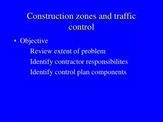
Outline • Project Design • Research Goals • Model Description and Assumptions • Model Validation • Hazardous Gas Mixtures • Hazard Mitigation • Modeling Parameters • N2 Injection and Explosive Mixtures • Spon Com and O2Concentration
Research Goals • Modeling of stratigraphy of longwall panel to establish gob resistance to gas flow • Modeling of sealed longwall panel – sealed, progressive nitrogen inertization, and gob vent boreholes • Validation of model utilizing available measurements • Explosive zones identified in the ventilated areas and gob • Partnerships with mines
Plan View – Sample Mine Outlet – (24 m sensor) Ventilation Inlet Nitrogen Inlet Nitrogen Inlets Gob GVBs
FLAC 3D Modeling • FLAC 3D used to model permeability and porosity in the gob. • Potential flow of gases in overlying strata – used as methane source in FLUENT. Assumed and Simplified Methane Source Vertical cross section of bed displacement and gob formation
FLAC 3D Modeling – Permeability Output • FLAC 3D Model takes into account overburden material strengths to determine stress and strain distribution in gob. • Converts stress and strain to porosity and then permeability distribution.
Full Panel Resistance – FLAC to FLUENT 50 % 40 % 4800 ft 2400 ft 7200 ft 9600 ft 30 % HG 20 % TG 10 % 0 %
Final Cross Sectional Geometry GVB Methane Inlet Upper Coal Seam 6 ft Fractured Zone 127 ft Void Entries 43 ft Gob Tailgate
Model Validation • Quantity and gas concentration readings at ventilation network evaluation points (intake, face, return) • Sampling ports at seals (O2, N2, CO, CO2, CH4) • Gob ventilation boreholes (O2, N2, CO, CO2, CH4, flow) • Tracer gas studies (NIOSH)
Gob Gas Explosibility Color Coding O2 Concentration CH4 Concentration TG HG Plan View
Hazard Mitigation Parameters • Face Ventilation Rates • Hazardous Gas Mixture • Oxygen Ingress and Spon Com Risk Assessment • Nitrogen Injection Studies • Hazardous Gas Mixture • Oxygen Ingress and Spon Com Risk Assessment • Gob Caving Characteristics
Face Ventilation Quantity Impact 70,000 cfm 40,000 cfm TG HG TG HG
Higher Face Quantities Increase Explosive Mixture Volume in the Gob
Oxygen Ingress – Face Quantity 70,000 cfm (33 m3/s) 400 cfm (0.19 m3/s) 400 cfm (0.19 m3/s) 30.5 m 100 ft 14
Oxygen Ingress – Face Quantity Face Ventilation Quantity of 40,000 cfm (19 m3/s) 40,000 cfm (19 m3/s) 400 cfm (0.19 m3/s) 400 cfm (0.19 m3/s) 30.5 m 100 ft 15
Nitrogen Injection Effect • Base case used 70,000 cfm of face ventilation and 400 cfm of nitrogen injection HG and TG • Evaluated impact of nitrogen injection • Quantity (200 – 1600 cfm) • Location (HG vs. TG) • Purpose is to minimize volume of explosive methane-air mixture
Nitrogen Injection Rate Study 200 cfm HG & TG 800 cfm HG & TG HG TG HG TG
Nitrogen Injection Location Study TG HG TG HG 800 cfm N2 Injection 200 cfm 200 cfm N2 Injection 800 cfm
Oxygen Ingress – Nitrogen Injection Rates Headgate ONLY Nitrogen injection – HG = 200 cfm (0.09 m3/s) 70,000 cfm (33 m3/s) 0 cfm (0 m3/s) 200 cfm (0.09 m3/s) 30.5 m 100 ft 20
Oxygen Ingress – Nitrogen Injection Rates Headgate ONLY Nitrogen injection – HG = 800 cfm (0.38 m3/s) 70,000 cfm (33 m3/s) 0 cfm (0 m3/s) 800 cfm (0.38 m3/s) 30.5 m 100 ft 21
Oxygen Ingress – Nitrogen Injection Rates Headgate ONLY Nitrogen injection – HG = 1600 cfm (0.75 m3/s) 70,000 cfm (33 m3/s) 0 cfm (0 m3/s) 1600 cfm (0.75 m3/s) 30.5 m 100 ft 22
Oxygen Ingress – Nitrogen Injection Rates High Nitrogen injection rate – HG = 800 cfm (0.38 m3/s), TG = 800 cfm (0.38 m3/s) 70,000 cfm (33 m3/s) 800 cfm (0.38 m3/s) 800 cfm (0.38 m3/s) 30.5 m 100 ft 23
Oxygen Ingress – Nitrogen Injection Rates High Nitrogen injection rate – HG = 1600 cfm (0.75 m3/s), TG = 800 cfm (0.38 m3/s) 70,000 cfm (33 m3/s) 800 cfm (0.38 m3/s) 1600 cfm (0.75 m3/s) 30.5 m 100 ft 24
Conclusions • Increasing the face ventilation quantity pushes oxygen further into the gob • This may increase the volume of explosive gases • This may increase spon com tendencies • Injecting nitrogen to inertize is most effective from the headgate but some nitrogen should also be injected on the tailgate side • Nitrogen will reduce explosive gas volume • Nitrogen will reduce spon com hazard
Questions or Comments • Dr. Jürgen F. Brune Research Professor COLORADO SCHOOL of MINES • 303-273-3704 • jbrune@mines.edu Thank You