Download

1 / 35
350 likes | 456 Views
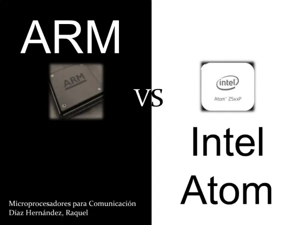
Samsung ARM S3C4510B. Product overview System manager Unified instruction/data cache I2C bus controller Ethernet controller 32-bit timers I/O Ports Interrupt Controller. Product overview. S3C4510B 16/32-bit RISC

E N D
Samsung ARM S3C4510B Product overview System manager Unified instruction/data cache I2C bus controller Ethernet controller 32-bit timers I/O Ports Interrupt Controller
Product overview • S3C4510B • 16/32-bit RISC • Cost-effective, high-performance microcontroller solution for Ethernet-based system • S3C4510B built an outstanding CPU core • 16/32-bit ARM7TDMI RISC processor • TDMI means Thumb mode, Debugger core, faster Multiplier, embedded ICE logic
Introduction to AMBA • AMBA: Advanced Microcontroller Bus Architecture • Three distinct buses are defined within the AMBA specification: • the Advanced High-performance Bus (AHB) • for high-performance, high clock frequency system modules. • acts as the high-performance system backbone bus. • supports the • efficient connection of processors, on-chip memories and off-chip external memory interfaces with low-power peripheral macrocell functions. • the Advanced System Bus (ASB) • for high-performance system modules. • suitable for use where the high-performance features of AHB are not required. • the Advanced Peripheral Bus (APB). • for low-power peripherals. • optimized for minimal power consumption and reduced interface complexity to support peripheral functions.
Product overview • Integrated the following on-chip functions • 8k-byte unified cache/SRAM • I2C interface • Ethernet controller • HDLC • GDMA • UART • Timers • Programmable I/O ports • Interrupt Controller
Product Overview - Features • Architectures • Embedded in Circuit emulator (ICE) • Little/big-endian mode supported (Internal architecture is big-endian) • System manager • 8/16/32-bit external bus support for ROM/SRAM, flash memory, DRAM, and external I/O, Support EDO/normal or SDRAM • Four-word depth write buffer • Cost-effective memory-to-peripheral DMA interface • Unified instruction/data cache • Two-way set-associative, unified 8k-byte cache • Support for LRU (least recently used) replacement protocol • I2C serial intrface • Ethernet controller (10/100-Mbps full-duplex) • HDLC • DMA controller (2-channel general DMA) • For memory-to-memory, memory-to-UART, UART-to-memory • UARTs (two UART with DMA-based or interrupt-based operation) • Timers (two 32-bit timers with interval mode or toggle mode operation) • Programmable I/O (18 programmable I/O ports) • Interrupt controller (21 interrupt sources, includes 4 external interrupt)
System manager • Handle the following functions • Decide little and big endian for external memory or I/O devices • To enable the cache function or not • For the external memory operations (6 ROM/SRAM/Flash memory banks, 4 normal/EDO DRAM or SDRAM banks, and 4 I/O bank) • Memory bank locations • External bus width access cycle • Control signal timing (Ex: RAS, CAS) • The size of memory banks to be used for arbitrary address spacing • The address resolution for each memory bank base pointer is 64k-bytes (16 bits) • The base address pointer is 10 bits for each memory banks (therefore, the total address space for memory bank space is 16 M words)
System memory map • The size and location of each memory bank is determined by • Current bank base pointer • Start address: base pointer << 16 • Current bank end pointer (next pointer) • End address: end pointer << 16 -1 • The maximum access memory space for each memory bank is 4 Mbytes • The address boundaries of consecutive banks must not overlap • For external I/O banks are defined in a continuous address space • Only set the base pointer of external I/O bank 0 • The start address of external I/O bank 1 is bank 0 start address + 16K • After power-on or system reset • All bank pointers except for the next pointer of ROM bank 0 are set to zero • The next pointer and the base pointer of ROM bank 0 are 0x200 and 0x000 (is 32-Mbyte space with a start address of zero 64K 16K
External address translation depends on the width of external memory
Connection of external memory with various data width • When the CPU issues an arbitray address to access an external memory device • The CPU compares the upper 10 bits of the issued address with the address pointers of all memory banks • When the bank is identified and the offset has been derived, the corresponding bank selection signal (nRCS[5:0] or nECS[3:0]) is generated, and the derived offset is driven to address external memory through the physical address bus
Control registers: system configuration register (SYSCFG) • Determine the start address of the system manager’s special registers • Start address of internal SRAM • Enable the write buffer • Cache enable and cache mode • Stall enable operation • All DRAM banks set to the synchronous DRAM (SDRAM) mode
Start address setting • If a reset initialize the start address to 3FF0000H • The offset address of the ROMCON register is 3014H • The physical address for ROMCON is 3FF0000H + 3014H = 3FF3014H • Cache disable/enable • To enable or disable the cache • Does not have an auto-flush feature (not auto write-back) • The memory area that is allocated to DMA access operation must be non-cachable (don’t maintain cache coherence problem) • Internal 8-Kbyte SRAM can be used as a cache area or normal SRAM according to the CM field (cache mode) • The address of internal SRAM is set by internal SRAM base pointer field • Write buffer disable/enable • Four programmable write buffer registers • To maintain data coherency between the cache and external memory, the S3C4510B uses a write-through policy
Data bus with register (EXTDBWTH) • Allow interface for 8/16/32-bit external ROMs, SRAMs, flash memories, DRAMs, SDRAMs, and external I/O ports
ROM/SRAM/FLASH control registers (ROMCON) • Has six control registers for ROM, SRAM, and flash memory • The external data bus width of ROM/SRAM/Flash bank 0 is determined by the signal at the B0SIZE[1:0] pins
ROM bank 5 address/data multiplexed bus • The S3C4510B has separate address and data bus • S3C4510B supports multiplexed address/data bank (ROM bank 5) which can support address/data multiplexed bus and 4-data burst access by GDMA. For this feature, you should set the MUX enable bit and wait enable bit of CLKCON register • Four-data burst access by GDMA • When FB (4-data burst enable) bit in the GDMACON register, the GDMA request 4-data burst access. • When you access ROM bank 5 by 4-data burst mode, the multiplexed ROM bank 5bus has only one address phase
Unified instruction/data cache • The S3C4510B CPU has a unified internal 8K byte instruction/data cache. • Using cache control register settings, you can use part or all of this cache as internal SRAM • The cache is configured using two-way, set-associative addressing • The replacement algorithm is pseudo-LRU (least recently used) • The cache line size is four words (16 bytes) • Cache configuration • If cache size is 4 kbyte, two-way set associative instruction/data cache uses a 15-bit tag address for each set (line) • The CS bits is tag memory stores information for cache replacement • When a reset occurs, the CS value is 00 (set 0 and 1 is invalid) • The first cache fill after the reset, the CS value become 01 (set 0 is valid, set 1 is invalid)
Cache disable/enable • Set SYSCFG[1] to “0” can disable cache • Cache flush operation • To flush the cache line • Write a zero to tag memory bits 31 and 30, respectively • The 4-Kbyte set 0 RAM area, 4-Kbyte set 1 RAM area, and the 1-Kbyte Tag RAM area (total 356 words) can be accessed from locations 0x10000000h, 0x10800000h, and 0x11000000h, respectively • Tag RAM is normally cleared by hardware following a power-on reset • If the cache or memory bank configuration is changed and the cache is enabled • The application program must clear the Tag RAM area • Non-cacheable area control bit • If ADDR[26] in the ROM/SRAM, flash memory, DRAM, or external I/O bank’s access address is “0”, then the accessed data is cacheable • If the ADDR[26] value is “1”, the accessed data is non-cacheable