Download
1 / 23
230 likes | 366 Views
Status of Front-end Unification. DAQ Meeting at Belle-II Meeting 7-JUL-09. Gary Varner. Today’s Update. Since March meeting: Discussion in Beijing (RT09 at IHEP) Action/inaction on part b Continued (TARGET, BLAB2 eval) Specifying KLM needs (Si-PM gain)

E N D
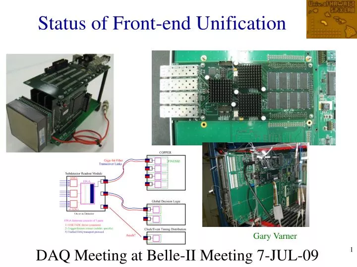
Status of Front-end Unification DAQ Meeting at Belle-II Meeting 7-JUL-09 Gary Varner
Today’s Update • Since March meeting: • Discussion in Beijing (RT09 at IHEP) • Action/inaction on part b • Continued (TARGET, BLAB2 eval) • Specifying KLM needs (Si-PM gain) • System timing limitations for PID BLAB3 • Giga-bit link test results, plans
Refining Proposal Proposed Common Approach for Belle++
Common protocols User code?
Waveform sampling “everywhere”? What about the Front end?
Possible ASIC Options(presented previously) Future? TARGET2a (?) TARGET2 BLAB3 BLAB3
TARGET KLM – Si-PMs User Feedback Dmitri Liventsev (ITEP) Jerry Va’vra (SLAC)
Baseline System Components • BLAB3 is 8 channels, each 64k samples deep • <~1us to read out 32-samples hit/BLAB3 Giga-bit Fiber MCP MAIN BLAB3 Photo- Sensor x4 x4 BLAB3 FINESSE CARD COPPER FIFO BLAB3 Photo- Sensor BLAB3 Focusing on these prototypes – results next time
Significant cost and performance benefit if can use commercially available components. One option is to qualify them. Concerns about rad hardness:proposal ~25 m Fiber link Monitor continuously BER remotely (loopback of pseudo-random pattern) In tunnel (rad area simulating expected CDC/PID dose) • Proposed to run test link • In KEKB tunnel (installed Mar.) • Reprogram rate • Fiber link degradation
xTOP Readout Baseline System Components Testing this part • BLAB3 is 8 channels, each 64k samples deep • <~1us to read out 32-samples hit/BLAB3 MCP MAIN BLAB3 Photo- Sensor x4 x4 BLAB3 FINESSE CARD COPPER FIFO BLAB3 Photo- Sensor BLAB3 Giga-bit Fibers
Near Oho-side of Belle endcap, Ring outside direction, on Shielding wall Test Location Fiber link runs Through existing Cable tray infrastructure and to loss monitor rack in room below
Existing coaxial loss monitor (instantaneous dose) Concurrent Monitoring 2x Aminogray (integral radiation dose) Giga-bit Fiber Transceiver Virtex-2 Pro FPGA w/ Rocket I/O
USB2 connection to Monitor PC “COPPER” end Giga-bit Fiber Same transceiver board as test side
Monitoring Station Local error logging, accessible remotely via KEKB network • Write alternating pattern of 1’s and 0’s • (~130k RAM bits, 8k Reg bits total) • Wait 1 second, then read back • Check pattern for corruption • Log number of bit errors seen DAQ machine Thanks, John!
Local error logging, accessible remotely via KEKB network Monitoring Details • Since start of beam, ~1M write/read cycles • No bit errors seen (bug fixed, tested) • BER <~10-11 Stop/restart program about every 3-7 days (~2MB/day)
First induced errors ~0.4% of events No RAM bit errors Number of bits error
Constant pattern ~0.4% of events No RAM bit errors ~May 10 (00:18)
Rad-test Summary Did power cycle (and subsequent firmware reload) on May 17 • Ran fine through end of Experiment 69 (1x RAM bit errors) since successful re-program [4.37M events] • Errors probably isolated to a subset of FPGA firmware -- cleared by power cycle • Concern about voltage regulators (replace for autumn run?) • Goal: need to address radiation hardness concerns soon perhaps OK; ~11.6kRad (10.8kRad/12.5kRad)
Plans • BLAB3 (PID) ASIC fabrication in August • TARGET2 almost same (with amp), KLM • Manpower limit for CDC ASIC version • Front-end prototypes fabricated and gaining experience with operation; trying to address questions • Prototypes of a version of “unified readout” COPPER: (FIN_DSP, UFO, USO) in development • Instrument xTOP prototype; upgrade fDIRC, HI-TIDE readout set-ups (system timing, online processing)
Assume: 100kHz charged track hits on each bar Hit Processing latency • ~32 p.e./track (1% of 100ns windows) • 30kHz trigger rate • Each PMT pair sees <8> hits • 240k hits/s • Each BLAB3 has an average occupancy <1 hit (assume 1) • 400ns to convert 256 samples • 16ns/sample to transfer • At least 16 deep buffering • (Markov overflow probability • est. < 10-38) • Each hit = 64samples * 8bits = 512bits • ~125Mbits/s (link is 1.2Gb/s ~ x10 margin) BLAB3 ASIC Trans-Imp Amps 64 x 1k samples Per channel 8 BLAB3 sampling Fast conversion Matrix (x256) Improvements based upon Lessons learned from BLAB2 Plan to model in standard queuing simulator, but looks like no problem (CF have done same exercise with Jerry Va’vra for 150kHz L1 of SuperB and can handle rate)
128 DAQ fiber transceivers PID (iTOP) DAQ Summary 32 FINESSE 8 COPPER 16k channels 2k BLAB3 128 SRM