Download
1 / 18
180 likes | 320 Views
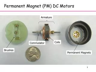
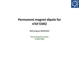
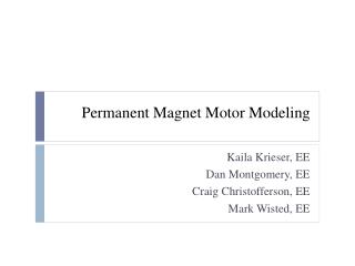
Permanent Magnet Option for ILC Final Doublet Quads and Tail Folding Octupole. Y. Iwashita, T. Mihara, S.Nakamura, M. Ichikawa, Y. Tajima, Kyoto University M.Kumada, NIRS C.M. Spencer, SLAC. 1. Adjustable Permanent Magnet Quadrupole Prototype for 20mr X’ing Angle. Permanent Magnet

E N D
Permanent Magnet Option for ILC Final Doublet Quads and Tail Folding Octupole Y. Iwashita, T. Mihara, S.Nakamura, M. Ichikawa, Y. Tajima, Kyoto University M.Kumada, NIRS C.M. Spencer, SLAC 1
Adjustable Permanent Magnet QuadrupolePrototype for 20mr X’ing Angle Permanent Magnet (NEOMAX38AH) 2
Bore radius 1cm Inner ring radii In 1cm out 3cm Outer ring radii In 3.3cm out 5cm Outer ring section length Physical length 1cm, 2cm, 4cm, 8cm 23cm Pole material Permendur Magnet material (inner ring) NEOMAX38AH Magnet material (outer ring) NEOMAX44H Integrated gradient (strongest) 24.2T Integrated gradient (weakest) 3.47T Int. gradient step size 1.4T Prototype Magnet Extra beam hole Inside View of Outer Ring Inner Ring Base plate Before assembly 3
Magnetic Center Movement The cm values show the Switched-On-Length The center moves several µm for 20% strength change. See http://accelconf.web.cern.ch/AccelConf/l04/PAPERS/TUP81.PDF (LINAC’04) 4
Demonstrate a higher field gradient by reducing the bore size from ø20mm down to ø15mm. Recent Modification Temperature compensation of the inner ring; 1 mm (left) and 1.6 mm (right) MS-1 trapezoidal plates are seen in a 2cm space between magnets. 5
Longitudinal Distribution Vertical component By measured along Z by a Group3 Tesla meter. dz = 2mm, z = 0 ~ 380mm dx, dy = ±2mm Bore: ø15mm 6
Bore ø15mm All OFF Longitudinal Distribution All ON T/m T/m Centroid Centroid Z [mm] Z [mm] Almost flat: Gmax ~190T/m Gmin ~ 29T/m 7
SWL = 4cm SWL = 8cm T/m Centroid T/m Centroid Centroid Centroid Z [mm] Z [mm] Gradient is high at ON region. Magnet gaps of the inner ring affects the distribution. 8
0 5 10 15 Integrated Strength (GL): ∫G dz [T] 40 35 30 25 20 15 10 5 GL value is proportional to the SWL: GLmax ~ 38 T GLmin ~ 5.9T @ø15,L=23cm SWL [cm] 9
5 10 15 0 50 Cases of only 8cm (entrance) ON or only 4cm(exit) ON shows the maximum and minimum. Magnetic field centroid mm -50 Centroid location as a function of SWL The excursion of the centroid is almost half of its length; it can be reduced by using a couple of PMQ’s back to back. 10
Eff.L m Radius m PoletipB kG Gradient kG/m IntG.dl kG QF1 2.0 0.010 8.0 803 1605 QD0 2.2 0.010 -14.2 -1416 -3116 QDEX1 1.1 0.015 -15.0 -1000 -1060 Required spec’s for Final Focus Variable PMQ will generate 1400kG/m, but 14mrad. case needs more study. Brett Parker's sketch of how they be placed as sc. quads 11
GLD SiD SiD (by Takahashi) neutron BeamCAL 17mW 13mW 29mW QD0 94mW 97mW 147mW 105 [n/cm2s] SD0 11mW 11mW 11mW QF1 16mW 18mW 15mW SF1 0.4mW 0.3mW 1mW Energy deposit Demagnetization by 14MeV neutron Demagnetization by Radiation T. Kawakubo, et al., The 14th Symposium on Accelerator Science and Technology, Tsukuba, Japan, November 2003, pp. 208-210, in Japanese, http://conference.kek.jp/sast03it/WebPDF/1P027.pdf very preliminary results by T.Abe (university of Tokyo), in private communication Continuous 1mo.(2.6x10⁶s) operation may cause about 0.01[%] of (reversible?) demagnetization on NEOMAX 32EH. (1% for 10 years) ... needs more info. 12
PM-Octupole for tail-folding Bore ø32, Size ø150 for ATF2 ILC: Baseline Sc design: 0.5T@pole tip, 1TeVCM PMO can be strong; shorter in length. 15
Mutlipole components Rotation of the ring may be analog not digital way. 16
Reduced skews Skew components can be canceled if two outer rings are incorporated and rotated in opposite direction. 17
Summary • Adjustable PMQ realizes 140T/m@ø20mm • The excursion of lens center was measured. • New config. may be possible for smaller cross section(Needs more idea and study including lattice design) • Demagnetization seems small (1% for 10 years?)maybe OK even if 10 times more, but needs more info. • Octupole for tail folding? • Will fabricate one model (Quad or Octupole)— may be tested in ATF2 18