Download
1 / 11
110 likes | 223 Views
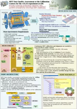
Detector Solenoid and Compensating Solenoid update. R. Appleby, B. Dalena , H. Gerwig , D. Swoboda , D. Schulte, R. Tomas . Field Computation. ILD D. Swoboda. R 25 cm L IP 3.5 m. SiD H. Gerwig. R 50 cm L IP 3.8 m. Longitudinal Field along the beamline.

E N D
Detector Solenoid and Compensating Solenoid update R. Appleby, B. Dalena, H. Gerwig, D. Swoboda, D. Schulte, R. Tomas
Field Computation ILD D. Swoboda R 25 cm LIP 3.5 m SiD H. Gerwig R 50 cm LIP 3.8 m
Dispersion Comparison Both the compensating solenoids cancel > 95% of the vertical dispersion due to the main detector solenoid.
Coupling Comparison Both the compensating solenoids cancel > 90% of the < x’, y > coupling due to the main detector solenoid.
Dynamic tolerances • Tolerances are defined using the beam-beam offset at the IP. • Two cases: • perfect aligned solenoid (a) • horizontally misaligned solenoid (i.e. misalignment of the longitudinal magnetic axis) (b) (a) • perfect aligned solenoid (0.25y) • B [8.65-10.0] e-5 • B 10. e-5 + Antisolenoid • B 0.8 e-5 + AntiDiD • (b) horizontally misaligned solenoid • B [5.7-7.9] e-5 • B 10.0 e-5 + Antisolenoid (b) • N.B. assumptions: • linear and homogeneous (along z) scaling of the fields • main solenoid and compensating solenoid scale together
Conclusion & Outlook • The two compensating solenoid perform in the same way from the beam optics point of view. Vertical dispersion and <x’,y> coupling due to main solenoid field reduced > 90% • Luminosity optimization for Incoherent Synchrotron Radiation might be required • Compensating solenoid can help in reducing the dynamic tolerances due to field instability (provided the field changes scale in the same way!) The residual vertical dispersion and <x’, y> coupling must be compensated • Optimization of the compensating solenoid • Using the other magnets of the FFS