Download
1 / 28
290 likes | 403 Views
High Resolution Array Detector. Design of Infrasound Detection and Parameter Estimation Systems Hein Haak & Läslo Evers June-September 2003. Design of the Infrasound network. Bulletin Localization Association to events Parameter estimation Signal detection Array layout Instruments.

E N D
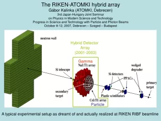
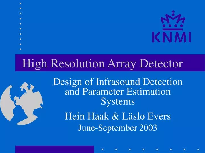
High Resolution Array Detector Design of Infrasound Detection and Parameter Estimation Systems Hein Haak & Läslo Evers June-September 2003
Design of the Infrasound network • Bulletin • Localization • Association to events • Parameter estimation • Signal detection • Array layout • Instruments System design Bulletin production, build-up, from IMS to IDC
Detectors / Estimators • Several detectors available: • F-detector • PMCC, MCCM • PWS phase-weighted stacks • LTA/STA … • Generally the detailed descriptions of the detectors could be improved, clear determination of ROCs could be added, black boxes are undesirable, transparency is needed • What is the relation between detector and array design
Basic design considerations • Hardware is hard to adjust, software is more flexible • Frequency wave number analysis is the standard • High resolution methods (Capon) are less robust at low S/N • Coherency detectors are used: Fisher, correlation, semblance throughout the network of arrays • Small arrays, higher resolution, lower costs • Detection without some parameter extraction or estimation is meaningless
What is “Performance” • Low missed event and false alarm rates (detection part of the problem) • Event parameters with small error bars (estimation part of the problem) • Low investment and operation costs leading to small dimensions of the array (cost efficiency)
Practical array design (1) • Suppose an array of 8 elements is confined to a 100 100 grid, then the system has 2.5 1027 independent realizations • A year contains 31.5 10 9 milliseconds • Brute force array design is not realistic • Even with only 50 independent positions there are 536,878,650 possible configurations • Alternative solutions are needed like genetic algorithms or Monte Carlo techniques • Only an approximate solution are possible • Symmetric approaches are generally not helpful
Practical array design (2) • If most of the array is fixed, for instance because of infrastructural circumstances additional elements can be placed strategically, to achieve a secondary optimum • With isotropic response • Angular resolution conform array diameter • Low side lobe amplitudes
Side lobes reducers Side lobes can be reduced through: • Broad frequency band in analysis • Use of Fisher statistics Hardware • Small diameter of the array • Many array elements • Optimal array design in detail Software Conclusion: side lobes should not be a problem
Resolution of arrays; theory • Consider Cramér-Rao Lower Bound • Separation of a signal/noise component and array geometry • Maximize moment of inertia: • Isotropic condition: • Resolution: • Leads to circular arrays with constant radii, the central element is not contributing to the resolution • In sparse arrays non-max-R elements contribute to lower side lobes
Main lobe / side lobe • amplitude vs. • number of elements • S-range: 0.005 sec/m • and 0.0075 sec/m • Resolution conform • diameter of 1200 m • The product: • ·Smax·B Const.
Array response 8 elements at 1 s period
Array response 8 elements at 4 s period
Array response 8 elements at 1 s period with side lobe penalty function
Array response 8 elements at 4 s period with side lobe penalty function
‘F’ • Calculation of the F-statistic from multiple time series Xct:
‘F’ • F in terms of coherent signal-to-noise power ratio: • Power is defined as the square of the amplitude
‘F’ • Calculation of the F-response: • FKResp. is the normalized FK-array response
‘F’ • Side lobe suppression: if any measured F-value is larger than Fside lobe then it is originating from the main lobe For R = 2.0, Fside lobe 7 with C = 8
Pentagonal array six elements • Relative small array in CTBT context • Radius 100 m • Small side lobes • S/N-power ratio: ~ 5.5 • 3 Hz, 110 m
Resolution with F-estimator This plot is made for white, Gaussian noise
A New CTBT Infrasound Array? Smaller array diameter More array elements Optimal detailed design Better adjusted to the detector