Download
1 / 43
430 likes | 570 Views
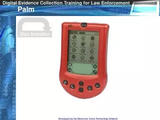
Wavertree Pillar Palm. Presented By: The University of Wisconsin Platteville Senior Design. The Design. Solidworks drawing of cast part after adding the parting line modifications to the bottom cylinder. The Design. Rivet Holes. Chamfer & Step.

E N D
Wavertree Pillar Palm Presented By: The University of Wisconsin Platteville Senior Design
The Design Solidworks drawing ofcast part after adding the parting line modifications to the bottom cylinder
The Design Rivet Holes Chamfer & Step Solidworks drawing of final product after all steps completed
Pattern Design Pattern Core • Mastercam drawing of pattern assembly • Core (lower half), Pattern (upper half)
Tool Path for Machining Tool paths for final machining of part Tool paths for machining cope half of pattern
Tool Path for Machining Start of machining program for cope of pattern as shown in Mastercam End of machining program for cope of pattern as shown in Mastercam
Solidification Modeling(MagmaSoft Program) Video of Solidification in MagmaSoft Niyama criterion in MagmaSoft
Solidification Modeling(MagmaSoft Program) Video of mold being filled using Magma
Machining Pattern Machining program for location holes as shown on the 2-axis CNC mill Machining program ½ done for cope of pattern as shown on the 4-axis CNC mill
Machining Pattern Program near finished for cope of pattern on 4-axis CNC mill Cope of pattern finished on 4-axis CNC mill
Machining Pillar Palm Fixture for machining step on bottom of part. Fixture for machining step on bottom of part with part on it.
Drilling Rivet Holes Fixture for machining holes in palm with part being machined ½” endmill milling holes after drilling operation
Machining Chamfer and Step Chamfer on bottom of part being machined Step on bottom of part being machined
Gating and Riser Design Foseco Riser Pillar Palms Gating
Gating and Riser (Cross Section) Foseco Riser Gating Pillar Palms
Solidification Modeling(Solidcast Program) Shows how casting solidifies after pour
A27 Steel Chemical Composition Required 5 test pours to obtain correct composition 5 test heats = 663 pounds of steel 14 Heats total = 1848 lbs melted Composition Equivalent to Mild Steel 0.192% Carbon (C) 0.974% Manganese (Mn) 0.794% Silicon (Si)
Personal Protective Equipment • Hard hat with shield • Safety glasses • Aluminized jacket • Aluminized apron • Aluminized spats • (cover legs and ankles) • Aluminized gloves • Steel toed shoes
PPE Required For Grinding • Hard hat with shield • Ear plugs • Safety glasses • Flame resistant jacket • Steel toed shoes
Coordinate Measurement Machine Inspected prototype Made positioning fixture Visited “Stainless Foundry and Engineering” for consulting Measured each casting for tolerances
Measurement Points • Centerline – center hole to center hole • Distance between • hole and center • line • Degree of angle • from center of • hole to centerline
Tensile Bar Testing Made keel blocks Machined tensile bars Pulled tensile bars tests Tensile strength Yield strength Elongation Results All parts met specification
Donations Make the Difference Without donations this project would not be possible
Thank You to our Donating Companies J. B. DeVENNE
Overhead Costs • Sand mixer and self centering vice • Increased mold making and machining efficiency • Sand mixer - $30,000 • Vice – complete donation
The Breakdown All costs included
No sand mixer, vice or labor included in total cost Platteville students are free labor The Breakdown
Facts and Figures • Resources Consumed • 8000 pounds of sand • 1800 pounds of slitter scrap (steel) • Over 2500 man hours • $1800 in purchased goods • $4400 donated by outside • firms
Thank You Dr. Kyle Metzloff Ph D. IS 4610 Professor Ray Monroe Steel Founders Society (SFSA) Philip Harrison Penumbra Design Benji Johnson Magma Soft Greg Gauerke Perfect Pattern – Core Box Build Scott Sharpee Neenah Foundry
The University of Wisconsin Platteville Thanks you for your support


![OLIVE BRANCH WAVERTREE RESIDENTS ASSOCIATION [OBWRA]](https://cdn1.slideserve.com/1852110/olive-branch-wavertree-residents-association-obwra-dt.jpg)