Download
1 / 100
1.01k likes | 1.03k Views
Explore recent trends in Rubidium frequency standard technology with detailed insights on Rb gas cell atomic clocks, optical pumping, historical perspective, and advances in RFS technology. Learn about commercial, military, and space applications of Rubidium clocks.

E N D
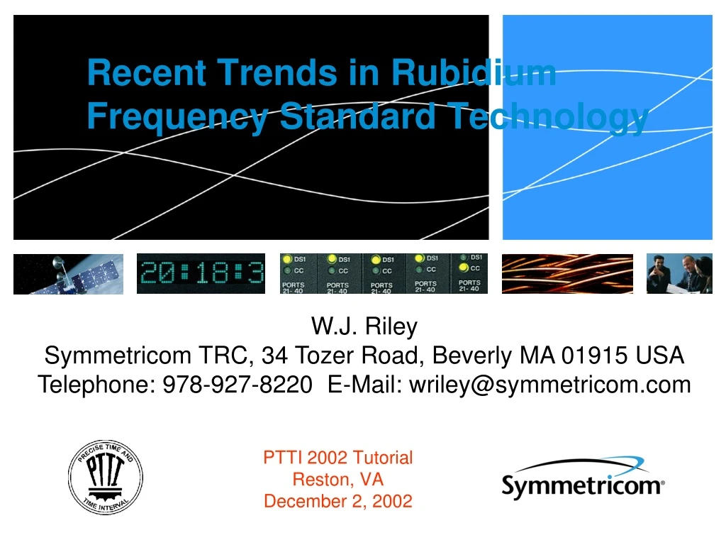
W.J. Riley Symmetricom TRC, 34 Tozer Road, Beverly MA 01915 USA Telephone: 978-927-8220 E-Mail: wriley@symmetricom.com Recent Trends in Rubidium Frequency Standard Technology PTTI 2002 Tutorial Reston, VA December 2, 2002
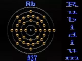
Rb Frequency Standards • Most Widely Used Type of Atomic Clock • Smallest, Lightest, Lowest Power, Least Complex, Least Expensive, Longest Life, Excellent Performance, Stability & Reliability • Device of Choice When Better Stability Than a Crystal Oscillator is Needed • Lower Aging, Lower Temperature Sensitivity, Faster Warm-up, Excellent Retrace, Lower Tip-Over Sensitivity, Lower Radiation Sensitivity Rubidium Gas Cell Atomic Frequency Standards PTTI 2002 Tutorial
Basic Block Diagram Basic Block Diagram of a Passive Atomic Frequency Standard PTTI 2002 Tutorial
Physics Package Rubidium Gas Cell Physics Package PTTI 2002 Tutorial
Optical Pumping Rubidium frequency standards use optical pumping by a Rb spectral lamp to create a non-equilibrium population difference between the two ground state hyperfine energy levels. This allows the hyperfine frequency to be measured by interrogating the atoms with microwave radiation and observing the change in light transmission through the cell. PTTI 2002 Tutorial
Hyperfine Filtration The efficiency of the optical pumping is enhanced by a fortuitous overlap between the optical absorption lines of the two naturally-occurring isotopes, 85Rb and 87Rb. This is the main reason that rubidium is used in most gas cell atomic frequency standards. PTTI 2002 Tutorial
Rb Freq Std Technology • Mature • Basic Principles Little Changed Since Late 1950’s • Optical Pumping, W Interrogation, Optical Detection, Synchronous Demodulation/Integration • Highly Refined • Stabilities Measured in pp1015 • Reduction of Light Shift, TC, Noise, Offsets, etc. • Modern Techniques • Digital Control, DDS, DSP, etc. • Emerging Physics • Laser Pumping, Cs Vs. Rb, CPT Interrogation PTTI 2002 Tutorial
Historical Perspective Early Pioneers whose Work Led to Today’s Rb Gas Cell Atomic Clocks PersonsYearPlaceWork A. Kastler 1950 Paris Optical pumping R.H. Dicke 1953 Princeton Buffer gas T.R. Carver 1957 Princeton Microwave detection H.G. Dehmelt 1957 Univ. Wash. Optical detection M. Arditi & T.R. Carver 1958 ITT, Princeton Optical detection, P.L. Bender, E.C. Beaty 1958 NBS buffer gas effects, TC, & A.R. Chi light shift, etc. T.R. Carver & C.O. Alley 1958 Princeton, NBS Isotopic filtering Much of this work was described in papers at the 1958 Frequency Control Symposium. Prototype RFS units soon followed in the early 1960’s as reported by Arditi & Carver, Carpenter, Packard & Swartz and others. Commercial units became available from Varian, Tracor, General Technology and others soon thereafter. A good reference to this early work is: M. Arditi and T.R. Carver, “The Principles of the Double Resonance Method Applied to Gas Cell Frequency Standards”, Proc. IEEE, pp. 190-202, January 1963. PTTI 2002 Tutorial
RFS Technology (Con’t) • Vigorous Developmental Activity • RFS Technology More Dynamic than for Other Atomic Clock Types • New Products Driven by Rapid Growth in Highly- Competitive Commercial Market • That Market is Large Enough to Support Continuing Technological Innovation Symmetricom X72 Rubidium Oscillator Atop Circa 1980 Efratom FRK Unit PTTI 2002 Tutorial
RFS Classes • Commercial • Small Size and Low Cost • Moderate Performance • Military/Aerospace • Environmental Hardening • Full Performance • Trend Toward COTS and PEMs • Space • High Performance • High Reliability Symmetricom X72 Symmetricom 8130A PerkinElmer GPS Block IIR RAFS [1] PTTI 2002 Tutorial
Commercial Rb Clocks • Small (X72 < 125 cc) • Inexpensive (< $1.5k) • Widely Used in Telecom Applications • Often Combined with a GPS Receiver to Form an Accurate, High Stability Time and Frequency Reference Stanford Research PRS10 [12] Frequency Electronics FE-5680A [13] Symmetricom X72 PTTI 2002 Tutorial
Military Rb Clocks • Small and Environmentally Hardened • Widely Used for Secure Communications • Classic Designs Used MIL Parts that are Now Hard to Obtain • Military Programs are Now Using Ruggedized Versions of COTS Units Classic Efratom M-100 MIL RFS - Circa 1980 Datum 8100 Ruggedized LPRO – Circa 2000 PTTI 2002 Tutorial
Military Rb Clocks (Con’t) • Military Programs are Also Using Modern Militarized RFS Units Designed Specifically for Rugged Applications that Use Lot-Qualified PEMs ( -40C) and Have Up-to-Date Features Like Digital Control Interfaces Symmetricom 8130A PTTI 2002 Tutorial
Space Rb Clocks • Usually Designed Specifically for Space • Vacuum Environment an Advantage • Radiation Hardening • Control/Monitor Interface Required • Isolated DC Power Return Usually Needed • S-Level Parts Usually Required • Extensive Analysis and Design Review • Extensive QTP/ATP Testing PerkinElmer GPS Block IIR RAFS [3] PTTI 2002 Tutorial
RFS Heritage in Space • Pre-GPS (1) • NTS-1 (Final Timation S/V) • GPS ( 200) • Blocks I, II, IIA, IIR, IIF (Underway) & III (Future) • Milstar ( 10) • Original and AEHF (Underway) • Science ( 5) • Cassini Huygens Probe • Other ( 0) • ETS, Galileo (Underway) The NTS-1 satellite that flew the 1st atomic clocks (2 Efratom FRKs) in space in July 1974 [9] Temex Galileo RAFS [5] PTTI 2002 Tutorial
RFS Space Applications • Provide Highest Performance • RAFS is Best GPS Clock where 24-Hour Stability is Critical • Overcome Crystal Oscillator Limitations • RFS Has Much Lower Aging • RFS Has Better Environmental Stability (Temperature, Radiation, etc.) • Use Proven Technology • Mature, Well-Understood, Reliable Age of Data, Hrs [10] PTTI 2002 Tutorial
Trends in RFS Technology • Digital Synthesis • DDS for Tuning and Modulation • Better Performance & Flexibility • Digital Control • DSP Servo Loop • Eliminate Analog Errors • Laser Pumping • Potential for Higher S/N and Stability • Diode Laser Noise & Reliability are Issues • No Laser-Pumped Products on Market Yet PTTI 2002 Tutorial
General RFS Evolution • Early Units (e.g. HP 5065) Emphasized Performance as Laboratory Standards • Integrated Cell Approach (e.g. Efratom FRS) Began New Evolutionary Path Toward Smaller, Cheaper, Lower Performance Units for Widespread Use • GPS Satellite Clock Requirements Led to Highest Performance Space Rb Clocks (e.g PerkinElmer RAFS) PTTI 2002 Tutorial
RFS Evolution (Con’t) • Early RFS designs were complex instruments with large physics packages, complex electronics, front panel controls, ovenized crystal oscillators. They generally had performance better than today’s commercial units, were made by the 100’s, and cost about the same as a family car. HP 5065 Laboratory RFS Circa 1970 [2] PTTI 2002 Tutorial
RFS Evolution (Con’t) • Today’s commercial RFS units are much simpler to build (thanks to more sophisticated designs and better electronic parts). They are plain boxes with enhanced functionality (e.g. GPS syntonization) and performance tailored to the application. They are made by the 10,000’s and cost only about 5% of a family car. And Mil-Spec Units Cost About 5% of a Mil-Spec Car! [14] PTTI 2002 Tutorial
RFS Evolution (Con’t) • The design of military/avionics RFS units has evolved less, mainly because the environmental conditions remain harsh. The trend is to leverage the economies of scale of commercial units (COTS, PEMs) to the greatest extent possible. Typical quantities are 100’s with prices about 25% of a family car. Symmetricom 8122 RFS module used in F-22 fighter aircraft Collins AFS-81Airborne RFS Circa 1972 [3] Ball Efratom M-3000 MIL RFS Circa 1985 PTTI 2002 Tutorial
RFS Evolution (Con’t) • Rb space clocks have evolved least of all from the original designs, but many small refinements have resulted in remarkable performance (pp1014 medium-term stability and daily aging rates). Each unit is individually crafted and tested at a cost equivalent to 10 or more family cars. General Radio/NASA SATS Spacecraft Atomic Timing System Circa 1965 [3] PerkinElmer GPS Block IIF RFS [1] PTTI 2002 Tutorial
Physics Package Evolution • Integrated Resonance Cell • Discrete -> Integrated Isotopic Filter • Smaller Microwave Cavity • TE011 -> TE111 -> Loaded, etc. -> Jin Resonator • Smaller, Hotter Cells • Inch -> cm -> mm Cell Dimensions • +65 -> +80 -> +95 Oven Setpoints • Optical Filter • Laser Pumping (Future) PTTI 2002 Tutorial
Filter Cells • The Rb-85 isotopic filter can be a separate cell, or combined with the Rb-87 absorption cell (likely using natural Rb which contains both isotopes). • Most RFS designs use the integrated approach because it is smaller and cheaper, and works well. Light shift can nulled by adjusting the isotopic ratio in the lamp. Temperature coefficient can be nulled by adjusting the buffer gas mixture in the cell. PTTI 2002 Tutorial
Filter Cells Con’t) • The main disadvantage of the integrated cell approach is high RF power shift caused by inhomogenity in the cell (the degree of isotopic filtering varies as the light passes through the cell, and the position of optimum signal varies with the RF power). • The separate filter cell allows light shift to be nulled by adjusting its length and/or temperature before the light enters the absorption cell, thus reducing the inhomogenity and RF power sensitivity. PTTI 2002 Tutorial
Filter Cells Con’t) • The absorption cell TC can be nulled with the buffer gas mixture, but the filter cell TC cannot. • But, if the separate filter and absorption cells are placed in the same oven, their net TC can be nulled, thereby allowing an overall optimization (zero light shift, zero TC, low RF power sensitivity). Example: EG&G RFS-10 [4] PTTI 2002 Tutorial
Microwave Cavities • Classic GR TE011 ( 80 cm3) • Classic EG&G TE111 ( 17 cm3) • FEI TE101 Rectangular, Dielectrically Loaded ( 5 cm3) • Temex Magnetron (L-C) Progressively Smaller Sizes TE011 TE111 [4] Temex Magnetron Cavity [5] PTTI 2002 Tutorial
Microwave Cavities (Con’t) • Northrop-Grumman TE201 Rectangular, Loaded, Scaled to Rb ( 3 cm3) • Jin Resonator (1 cm3) See U.S. Patent No. 6,133,800 (2000) Jin Resonator in X72 PTTI 2002 Tutorial
Jin Resonator The Jin Resonator is the enabling technology for making the X72 so small. 13=Resonator Assembly 23=Tuning Rod 26=Hole for Light 30=Rb Cell 31=Photodetector [6] PTTI 2002 Tutorial
N-G Miniature Cs Resonator A closely related cavity design was that of the highly innovative Circa 1995 Northrop-Grumman miniature Cs resonator. It used a 1.2 cm3 highly dielectrically loaded TE201 rectangular 9.2 GHz cavity in a 1.6 cm3 overall resonator assembly with a 0.1 cm3 cell. This scales to a 3.0 cm3 cavity for Rb at 6.8 GHz. Northrop Grumman Miniature Cs Resonator [7] PTTI 2002 Tutorial
Rb Gas Cells • The cells in the latest commercial RFS designs have (along with their cavities) gotten much smaller. While this comes at the expense of a broader line, lower Q and poorer short-term stability, good performance e.g. y()= 1x10-11 at 1 second can still be realized. Comparison between classic 1” long (LPRO) and latest ultra-miniature (X72) integrated Rb gas cells PTTI 2002 Tutorial
Cell Operating Temperature • The general trend has been toward higher Rb cell operating temperatures. • Higher cell operating temperature is associated mainly with the need to maintain the same optical absorption with a shorter cell length. • The main advantage of the higher oven setpoint is the ability to operate at higher ambient/baseplate temperatures (e.g. +85C for the Symmetricom X72). • Disadvantages include broader linewidth (lower Q and stability) higher power, longer warm-up time, and reduced reliability. PTTI 2002 Tutorial
Cell Temperature (Con’t) • Operation to high RFS baseplate temperatures was a difficult aspect of earlier MIL units. Various means were used to depress the Rb vapor pressure (natural Rb, K mixtures) or to actively cool the physics package. • The highest-performance GPS RAFS units use large cells operating at relatively low (+65C) temperature to achieve the best stability. Fortunately this is consistent with the S/V thermal conditions. PTTI 2002 Tutorial
RFS RF Chain Evolution • Complex Synthesis (Low Buffer Gas Offset) • Simpler Analog Synthesis (e.g. 5.3125 MHz) • DDS Synthesis • Flexible • Relaxed Cell Tolerance • High-Resolution Digital Tuning • Improved Servo Modulation PTTI 2002 Tutorial
RF Chain Evolution (Con’t) • Early RFS designs used complex synthesis schemes to achieve good microwave purity (low sideband pulling) and low buffer gas offset (low barometric sensitivity and comfortable fill tolerance). Essentially all RFS RF chains use a high-ratio step recovery diode (SRD) microwave multiplier because of its simplicity and the relatively low W power required. In many cases, the SRD multiplier is also used as a mixer. PTTI 2002 Tutorial
RF Chain Evolution (Con’t) • Experience showed that poorer purity and larger offset was acceptable, which allowed simpler synthesis schemes. A popular one only involved division by 16. The resulting 4.6 kHz offset was handled in some cases by measuring the cell frequency as it is filled. • Many other analog synthesis schemes have been used, often involving PLLs. An important consideration is how the servo modulation is applied (RC phase modulator, into PLL phase detector, direct VCO FM, etc.). In most cases, the modulation must be kept off the output signal. PTTI 2002 Tutorial
RF Chain Evolution (Con’t) • The advent of the 1-chip direct digital synthe-sizer (DDS) has greatly simplified RFS RF chains, making the cell offset a free variable, removing its tight fill tolerances, and offering an ideal way to apply servo modulation. As long as the DDS signal is inserted additively, 32 bit resolution is adequate for fine tuning. This has the additional advantage that the C-field can be held at a fixed minimum value for low magnetic sensitivity. PTTI 2002 Tutorial
RF Chain Evolution (Con’t) • The latest generation of commercial RFS RF chains use synthesis devices intended for the wireless industry. For example, IC PLL, quadrature modulator, and VCO chips can operate at 2.3 GHz (1/3 of the Rb frequency), thereby eliminating the high-ratio SRD multiplier (a simple diode tripler can be used instead). PTTI 2002 Tutorial
RF Chain Evolution (Con’t) • The need for frequency multiplication can be entirely eliminated by new high-speed digital dividers. This makes it possible to obtain a very pure W interrogation signal essentially free from pulling by sub-harmonics and mixing products. This technique is already being used in high-performance atomic clock designs. • All RFS RF chains must carefully consider the effect of phase noise on the interrogation signal. Noise at twice the servo modulation frequency is particularly important. PTTI 2002 Tutorial
Classic RF Chains • The majority of earlier-generation RFS RF chains generated the Rb hyperfine frequency of 6834.682611 MHz by multiplying a 5 or 10 MHz crystal oscillator to 6840 MHz and subtracting an offset of 5.3 MHz in a mixer. Often the microwave portion used an SRD multiplier as a combined multiplier and mixer. • Early RFS designs synthesized the 5.3 MHz offset to high precision to accommodate a low absorption cell buffer gas offset. This synthesis was either fixed (e.g. AFS-81) or variable (e.g. HP5065). The latter added considerable complexity, but provided more convenient tuning, reduced the required C-field range, and eased cell fill tolerances. PTTI 2002 Tutorial
Classic RF Chains (Con’t) • Many later RFS designs (e.g. Efratom FRK, M-100, etc.) used a simple fixed synthesizer wherein 5.3125 MHz was generated by dividing 5 MHz by 16 to 312.5 kHz and adding it to 5 MHz. This approach has a large buffer gas offset (4.9 kHz), and often had poor W spectral purity but, in practice, worked quite well. PTTI 2002 Tutorial
Efratom M-100 RF Chain PTTI 2002 Tutorial
Classic RF Chains (Con’t) • Better W spectral purity can be obtained by straight multiplication of an exact submultiple of the Rb frequency, usually from a phase-locked crystal oscillator in the 100 MHz region (e.g. The EG&G RFS-10 used 76 x 89.93007 MHz obtained as 90 MHz – 10 MHz/143). It is hard to make the offset variable because its steps are multiplied, reducing the resolution. PTTI 2002 Tutorial
EG&G RFS-10 RF Chain PTTI 2002 Tutorial
Classic RF Chains (Con’t) • The cleanest approach is to use a “natural frequency” configuration without any synthesis. This is rarely done because most systems require a standard (e.g. 10 MHz) reference. But a noteworthy exception is the PerkinElmer GPS Block IIR RAFS, which uses 13.40134393 MHz with a straight x510 (3·2·85) multiplier chain. PTTI 2002 Tutorial
PerkinElmer RAFS RF Chain PTTI 2002 Tutorial
New RF Chain Configurations • The 1-chip DDS has made variable RFS RF chain synthesis practical. For example, the Symmetricom 8130A uses the classic 5.3125 MHz final mix, but generates it with a 32-bit DDS (which also applies squarewave FM for the servo). A tuning resolution of 3.4x10⁻¹³ is obtained by separately adjusting both FM frequencies. PTTI 2002 Tutorial
Symmetricom 8130A RF Chain PTTI 2002 Tutorial
New RF Chains (Con’t) • Other modern RFS RF chain configurations can eliminate the high-ratio SRD multiplier by using new RF ICs and high-speed digital devices. The Symmetricom X72 uses a 2 GHz PLL chip, IC W VCO, SSB mixer, DDS, and diode tripler to generate its Rb interrogation signal. The latest Symmetricom Cs synthesizers use 9 GHz GaAs dividers with a phase-locked DRO, SSB mixer, and DDS to generate a very pure and stable signal. PTTI 2002 Tutorial
Symmetricom X72 RF Chain PTTI 2002 Tutorial