Download
1 / 16
160 likes | 259 Views
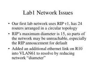
LAB1 Summary. Zhaofeng SJTU.SOME. Embedded Software Tools. CPU. Logic + Memory + IP + Processors + RocketIO (Virtex-II Pro ). CPU. Embedded Software Tools. Embedded Software Tools. FPGA + Memory + IP + High Speed IO (4K & Virtex ). Logic Design Tools. FPGA. Programmable Systems

E N D
LAB1 Summary Zhaofeng SJTU.SOME
Embedded Software Tools CPU Logic + Memory + IP + Processors + RocketIO (Virtex-II Pro) CPU Embedded Software Tools Embedded Software Tools FPGA + Memory + IP + High Speed IO (4K & Virtex) Logic Design Tools FPGA Programmable Systems usher in a new era of system design integration possibilities I/O Logic Design Tools Memory Logic Design Tools Integration in System Design Integration of Functions Time
IBM CoreConnect™ on-chip bus standard PLB, OPB, and DCR RocketIO Dedicated Hard IP DSOCM BRAM ISOCM BRAM Flexible Soft IP PowerPC 405 Core DCR Bus Instruction Data PLB OPB Bus Bridge Arbiter Arbiter Processor Local Bus On-Chip Peripheral Bus e.g. Memory Controller Hi-Speed Peripheral GB E-Net On-Chip Peripheral UART GPIO Off-Chip Memory ZBT SRAM DDR SDRAM SDRAM PowerPC-based Full system customization to meet performance, functionality, and cost goals
MicroBlaze 32-Bit RISC Core Possible in Virtex-II Pro OPB On-Chip Peripheral Bus Arbiter Custom Functions Custom Functions Memory Controller 10/100 E-Net UART MicroBlaze Processor-Based I-Cache BRAM Local Memory Bus Flexible Soft IP BRAM Configurable Sizes D-Cache BRAM Fast Simplex Link 0,1….7 CacheLink Off-Chip Memory FLASH/SRAM SRAM
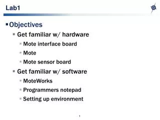
Embedded Design in an FPGA • Embedded design in an FPGA consists of the following: • FPGA hardware design • C drivers for hardware • Software design • Software routines • Interrupt service routines (optional) • Real Time Operating System (RTOS) (optional)
Embedded Development Kit • What is Embedded Development Kit (EDK)? • The Embedded Development Kit is the Xilinx software suite for designing complete embedded programmable systems • The kit includes all the tools, documentation, and IP that you require for designing systems with embedded IBM PowerPC™ hard processor cores, and/or Xilinx MicroBlaze™ soft processor cores • It enables the integration of both hardware and software components of an embedded system
VHDL or Verilog C Code Standard Embedded SW Development Flow Standard FPGA HW Development Flow Embedded Development Kit Code Entry HDL Entry C/C++ Cross Compiler Simulation/Synthesis Board Support Package System Netlist Data2MEM Linker Implementation Compiled ELF Compiled ELF Compiled BIT Compiled BIT ? ? Download Combined Image to FPGA Load Software Into FLASH Download Bitstream Into FPGA Debugger Chipscope Embedded DevelopmentTool Flow Overview Instantiate the ‘System Netlist’ and Implement the FPGA Include the BSP and Compile the Software Image 2 3 1 RTOS, Board Support Package
Embedded System Tools • GNU software development tools • C/C++ compiler for the MicroBlaze™ and PowerPC™ processors (gcc) • Debugger for the MicroBlaze and PowerPC processors (gdb) • Hardware and software development tools • Base System Builder Wizard • Hardware netlist generation tool: PlatGen • Software Library generation tool: LibGen • Simulation model generation tool: SimGen • Create/Import Peripherals Wizard • Xilinx Microprocessor Debug (XMD) • Hardware debugging using ChipScope™ Pro Analyzer cores • Eclipse IDE-based Software Development Kit (SDK) • Application code profiling tools • Virtual Platform generator: VPGen • Flash Writer utility
Embedded System Tools • Board Support Packages (BSPs) • Standalone BSP • Wind River VxWorks • MontaVista Linux • Xilinx MicroKernel (XMK) • Xilinx Platform Studio • Xilinx Platform Studio (XPS) is a graphical Integrated Design Environment (IDE) that incorporates all the Embedded System Tools for seamless creation of hardware and software components and, optionally, a verification component
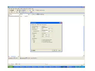
Xilinx Platform Studio (XPS) See notes section for detailed explanation
XPS Functions • Project management • MHS or MSS file • XMP file • Software application management • Platform management • Tool flow settings • Software platform settings • Tool invocation • Debug and simulation XPS HW/SW Simulation Hardware Design HW/SW Debug Software Design
Lab1 ESD on FPGA • Lab1.1 Simple Hardware Design • Lab1.2 Adding IP to a Hardware Design • Lab1.3 Adding Custom IP • Lab1.4 Writing Basic Software Applications • Lab1.5 Advanced Software Writing • Lab1.6 Cross Debugging
Create Embedded System using BSB Verify HW Operation with generated Test Application OPB Bus PLB Bus UART GPIO DIP Switches PLB2OPB PPC GPIO Push Buttons PLB BRAM Cntlr PLB BRAM MY IP LEDs PLB BRAM Cntlr PLB BRAM Timer INTC ICON IBA
Add GPIO Cores Add SW code to read state of DIP switches and Push Buttons and display on hyperterm OPB Bus PLB Bus UART GPIO DIP Switches PLB2OPB PPC GPIO Push Buttons PLB BRAM Cntlr PLB BRAM MY IP LEDs PLB BRAM Cntlr PLB BRAM Timer INTC ICON IBA
Summary • BSB can be used to create a simple processor system targeting a specific hardware board • Generates an MHS text file that describes the embedded system hardware • Generates a Test Application to test memory and peripherals • Platform generator converts the MHS to a system netlist • The ISE tools generate a bitstream from the system netlist • The bitstream was initialized with the software test application in EDK • The bitstream was downloaded to the XUP board • Output was displayed on hyperterminal
两点说明 • 外部管脚与UCF • 系统工作示意图