Download
1 / 57
570 likes | 834 Views
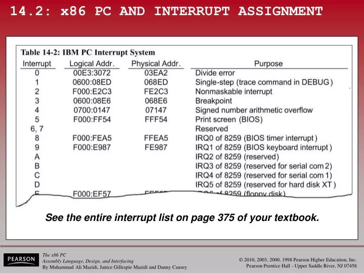
14.2: x86 PC AND INTERRUPT ASSIGNMENT. See the entire interrupt list on page 375 of your textbook. 14.2: x86 PC AND INTERRUPT ASSIGNMENT examining the interrupt vector table. Using DEBUG's dump command to examine the interrupt vector table of a x86 PC, regardless of CPU it contained.

E N D
14.2: x86 PC AND INTERRUPT ASSIGNMENT See the entire interrupt list on page 375 of your textbook.
14.2: x86 PC AND INTERRUPT ASSIGNMENT examining the interrupt vector table Using DEBUG's dump command to examine the interrupt vector table of a x86 PC, regardless of CPU it contained.
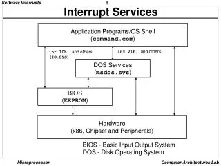
14.2: x86 PC AND INTERRUPT ASSIGNMENT examining the interrupt vector table • From the CS:IP address of the ISR, it is possibleto determine which source provides the service. • DOS or BIOS.
14.2: x86 PC AND INTERRUPT ASSIGNMENT analyzing an x86 interrupt service routine • The interrupt 12H service is available on any PC with an x86 microprocessor. • The job of INT 12H is to copy the value of the data area used by BIOS from memory locations 00413H and 00414H into AX and return. • A function of the BIOS POST is to test & count totalK bytes of installed conventional RAM, and write itin memory locations 00413H and 00414H • After INT 12H, AX will then contain the totalK bytes of conventional RAM memory.
14.2: x86 PC AND INTERRUPT ASSIGNMENT analyzing an x86 interrupt service routine Interrupt Service Routine in theIBM PC Technical Reference:
14.2: x86 PC AND INTERRUPT ASSIGNMENT INT 12H: checking the RAM size on the PC
14.2: x86 PC AND INTERRUPT ASSIGNMENT INT 12H: checking the RAM size on the PC
Figure 14-3 8259A Programmable Interrupt Controller 14.3: 8259 INTERRUPT CONTROLLER • x86 has only pins INTR& INTA for interrupts.
14.3: 8259 INTERRUPT CONTROLLER The Intel 8259 programmable interrupt controller (PIC) makes expansionof the number of hardware interrupts much easier. Figure 14-4 Partial Block Diagram of the 8259A
14.3: 8259 INTERRUPT CONTROLLERpins • CAS0, CAS1, and CAS2 - can be used to setup several 8259 chips to expand the numberof hardware interrupts to 64. • By cascading 8259 chips in a master/slave configuration. • To use 8259 in slave mode, the chip must be programmedand CAS0 to CAS2 are ignored. • SP/EN, slave programming/enable - in buffered mode, an output signal from 8259 to activate the transceiver (EN). • In nonbuffered mode, an input signal into the 8259. • SP = 1 for the master and SP = 0 for the slave.
14.3: 8259 INTERRUPT CONTROLLERpins • INT - an output connected to INTR of the x86. • INTA - input to the 8259 from INTA of the x86. • IR0 to IR7, interrupt request - hardware interrupts. • When a HIGH is put on any interrupt from IR0 to IR7,8088/86 will jump to a vector location. • For each IR there exists a physical memory locationin the interrupt vector table. • The x86 has 256 hardware or software interrupts.(INT 00–INT FF)
Figure 14-3 8259A Programmable Interrupt Controller 14.3: 8259 INTERRUPT CONTROLLERcontrol words and ports • Four control wordsassociated with the 8259: • ICW1 (initialization command word); ICW2; ICW3; ICW4. • There is only one address line A0 to communicate with the chip.
14.3: 8259 INTERRUPT CONTROLLERcontrol words and ports Table 14-3 and Example 14-7 show the values that A0 and CS must take to initialize the 8259.
14.3: 8259 INTERRUPT CONTROLLERcontrol words and ports • ICW1, initialization command word 1 - functions to make a distinction between ICW2, ICW3, and ICW4 when they are sent to the same address of 8259. • D0, LSB of ICW1, tells 8259 if it should look for ICW4or not. • If D1 is high, it knows the system is configured in slave mode should not expect any ICW3 in the initialization sequence. • Initialization must always start with ICW1, followed by ICW2, and finally the last one, if needed; there is no jumping ahead.
14.3: 8259 INTERRUPT CONTROLLERcontrol words and ports • ICW1, initialization command word 1. D2 is always set low (= 0) for x86. D3 chooses between level triggering or edge triggering of the input signals IR0–IR7. D4 must always be high. D5, D6, and D7 are all low for x86 processors. Figure 14-5 ICW Formats (ICW1 and ICW2)for the 8259
14.3: 8259 INTERRUPT CONTROLLERcontrol words and ports • ICW2, initialization command word 2 - assigns interrupt numbers to IR0–IR7. • The 8-bit INT type number assigned to the corresponding IR0 through IR7 is formed by the lower three bits D3–D7. (T3 through T7) • Lower three bits, D0, D1, and D2, vary from 000 to 111.
14.3: 8259 INTERRUPT CONTROLLERcontrol words and ports • ICW2, initialization command word 2. D3–D7 can only be programmed according to the assignment ofthe INT type. The lower bits are provided by 8259, depending on which interrupt of IR0 to IR7is activated. Figure 14-5 ICW Formats (ICW1 and ICW2)for the 8259
14.3: 8259 INTERRUPT CONTROLLERcontrol words and ports • ICW3, initialization command word 3 - used only when two or more 8259s are cascaded. • A single 8259 can be connected to eight slave 8259s. • In cascade mode, there are separate ICW3 wordsfor the master and the slave. • ICW4, initialization command word 4 - D0 indicates the processor mode. (PM) • D0 equals 1 for the 8088/86 and 0 for the 8080/8085. • D1 is AEOI (automatic end of interrupt), is high it eliminates the need for an EOI instruction to be present before the IRET (interrupt return) instruction in the interrupt service routine.
14.3: 8259 INTERRUPT CONTROLLERcontrol words and ports The 8259 can work in either buffered or nonbuffered mode. Figure 14-6a & b ICW Formats (ICW3 and CW4)for the 8259 - Master & Slave
14.3: 8259 INTERRUPT CONTROLLERcontrol words and ports SFNM, special fully nested mode must be used when8259 is in master mode, Figure 14-6a & b ICW Formats (ICW3 and CW4)for the 8259 - Master & Slave
14.3: 8259 INTERRUPT CONTROLLERmasking/prioritization IR0–IR7 interrupts What happens if more than one of interruptsIR0–IR7 is activated at the same time? Can we mask any of the interrupts? What about responding to another interruptwhile an interrupt is being serviced?
There are three operation command words:OCW1, OCW2, OCW3. 14.3: 8259 INTERRUPT CONTROLLERoperation command word OCW • After ICW1, ICW2, and ICW4 have been issued to initialize the 8259, 8088/86 is ready to receive hardware interrupts through 8259's IR0–IR7 pins. • After the process of initialization, the operation command word, OCW, can be sent to mask any of IR0–IR7, or change the priority assigned to each IR.
14.3: 8259 INTERRUPT CONTROLLERoperation command word OCW • With the help of OCWs, a programmer can dynamically change the priority associatedwith each of IR0–IR7, or mask any of them. • Example 14-9 shows how OCWs are sent to the 8259.
14.3: 8259 INTERRUPT CONTROLLERoperation command word OCW Three registers ofnote in the 8259: ISR(in-serviceregister) IRR(interruptrequest register) IMR(interruptmask register) Figure 14-4 Partial Block Diagram of the 8259A
14.3: 8259 INTERRUPT CONTROLLERoperation command word 1 OCW1 OCW1 is used to mask any of IR0–IR7. Logic 1 is for masking. (disabling) Logic 0 is for unmasking. (enabling) Figure 14-7 OCW Format for 8259A
14.3: 8259 INTERRUPT CONTROLLERoperation command word 1 OCW1 Figure 14-7 OCW Format for 8259A
14.3: 8259 INTERRUPT CONTROLLERoperation command word 2 OCW2 • OCW2 - used to assign a specific priority to the IRs. • Fully nested default mode - assigns the highestpriority to IR0 and the lowest to IR7. • 8259 can be programmed to change the defaultmode to assign the highest priority to any IR. • Specific rotation mode - 8259 can be programmed to make rotation follow a specific sequence rather thanIR0 to IR7. • The IR served will be stamped as the lowest priority, and willnot be served until every other request has had a chance.
14.3: 8259 INTERRUPT CONTROLLEREOI end-of-interrupt command • Assume an 8259, initialized, in the default fully nested mode (IR0 has highest priority; IR7 lowest). • IR3 is activated, and the CPU acknowledges theinterrupt by sending back a signal through INTA.
14.3: 8259 INTERRUPT CONTROLLEREOI end-of-interrupt command • Assume an 8259, initialized, in the default fully nested mode (IR0 has highest priority; IR7 lowest). • The CPU goes to the vector table and gets CS:IP of the interrupt service routine and starts to execute the routine.
14.3: 8259 INTERRUPT CONTROLLEREOI end-of-interrupt command • Assume an 8259, initialized, in the default fully nested mode (IR0 has highest priority; IR7 lowest). • Issuing EOI to 8259 indicates IR3 servicing complete, and the bit associated with IR3 in ISR can be reset to zero
14.3: 8259 INTERRUPT CONTROLLEREOI end-of-interrupt command • Assume an 8259, initialized, in the default fully nested mode (IR0 has highest priority; IR7 lowest). • The last three instructions of any interrupt service routine for IR0–IR7 must be issuing the EOI, followed by IRET.
14.3: 8259 INTERRUPT CONTROLLEROCW3 • OCW3 is used read 8259 registers IRR (interrupt request register) & ISR (in-service register). • D0 and D1 allow the program to read these registersin order to see which of IR0–IR7 is pending for service and which one is being served.
14.4: USE OF THE 8259 CHIP IN x86 PCs Interfacing 8259 to the IBM PC Two port addresses must be assigned to the 8259:One for ICW1; the second for ICW2/ICW4. Since the chip select is activatedby Y1 and all the x's for don't caremust be zero, the addresses canbe calculated in the mannershown.
14.4: USE OF THE 8259 CHIP IN x86 PCs 8259 initialization words in the PC • Configuration for the control words ICW1, ICW2, and ICW4 can be calculated:
INT 08 is for IRQ0, INT 09 is for IRQ1, etc. 14.4: USE OF THE 8259 CHIP IN x86 PCs 8259 initialization words in the PC • PC designers assigned INT 08–INT 0F for expansion of hardware interrupts. • Used by 8259 IR0–IR7, commonly called IRQ0–IRQ7.
14.4: USE OF THE 8259 CHIP IN x86 PCs 8259 initialization words in the PC • ICW2 informs 8259 which interrupt numbersare assigned to IRQ0–IRQ7. • By equating 8259 ICW2 to the interrupt assigned to IRQ0. • ICW2 is the interrupt number for IR0, in the IBM PC, INT08. • The 8259 is only programmed for the value of IRQ0, so the 8259 generates the INT numbers for IR1 through IR7. • ICW3 is used only when multiple 8259 chips are connected in master/slave mode.
14.4: USE OF THE 8259 CHIP IN x86 PCs 8259 initialization words in the PC • ICW4 configuration: • Gives the following code for 8259 initialization:
14.4: USE OF THE 8259 CHIP IN x86 PCs 8259 initialization • Once the 8259 is initialized, it is ready toaccept an interrupt on any inputs IRQ0–IRQ7. • Expanding the number of hardware interrupts. • The 8259 is tested by a program in BIOS duringthe POST (power on self test).
14.4: USE OF THE 8259 CHIP IN x86 PCs sequences of 8259 hardware interrupts • Sequence of events after an 8259 IR is activated. • 1. After an IR is activated, the 8259 will respond by putting a high on INTR. • Signaling the CPU for an interrupt request. • 2. 8088/86 puts the appropriate signals on S0, S1 & S2 (S0 = 0, S1 = 0, and S2 = 0), indicating to the 8288 that an interrupt has been requested. • 3. The 8288 issues the first INTA to the 8259. • 4. The 8259 receives the first INTA and does internal housekeeping, which includes resolution of priority, and resolution of cascading. • 5. The 8288 issues the second INTA to the 8259.
14.4: USE OF THE 8259 CHIP IN x86 PCs sequences of 8259 hardware interrupts • Sequence of events after an 8259 IR is activated. • 6. On the second INTA pulse, 8259 puts a single interrupt vector byte on the data bus in which 8088/86 will latch. INTR. • The value of the single byte depends on ICW2 andwhich IR has been activated. • 7. 8088/86 uses this byte to calculate the vector location, which is four times the value of the INT type.
14.4: USE OF THE 8259 CHIP IN x86 PCs sequences of 8259 hardware interrupts • Sequence of events after an 8259 IR is activated. • 8. 8088/86 pushes the flag register onto the stack, clears IF (Interrupt Flag) & TF (Trap Flag), disabling further external interrupt requests and single-step mode. INTR. • And pushes the present CS:IP registers onto the stack. • 9. The 8088/86 reads CS:IP of the interrupt service routine from the vector table and begins execution of the interrupt routine.
14.4: USE OF THE 8259 CHIP IN x86 PCs sources of hardware interrupts • With the 8259, the PC has eight interrupts. • IR0 to IR7, plus NMI of the 8088/86. • IBM has used two for internal use by the system. • IR0 - for channel 0 of the 8253 timer to updatethe time of day (TOD) clock, • IR1 - dedicated to the keyboard. • IR2 through IR7 are available through the expansion slots. • The following interrupts are used on the motherboard: • INT 08 IRQ0 Channel 0 of 8253 timer to update TOD • INT 09 IRQ1 Keyboard input data
14.4: USE OF THE 8259 CHIP IN x86 PCs sources of hardware interrupts Figure 14-9PC Sources of Hardware Interrupts
14.4: USE OF THE 8259 CHIP IN x86 PCs sources of NMI • The NMI, nonmaskable interrupt, is a CPU pin, and cannot be masked (disabled) by software. • There are three sources of activation of the NMI: • 1. NPIRQ. (numerical processor interrupt request) • 2. Read/write PCK. (parity check) • 3. IOCHK. (input/output channel check) • The PC recognizes which of interrupt requests has been activated by checking input port C of the 8255.
14.4: USE OF THE 8259 CHIP IN x86 PCs sources of NMI NMI is masked by a RESETsignal from the CPU withCLR of the D flip-flop whenthe computer is turned on. Figure 14-10 Sources of NMI in the PC
14.5: MORE ON INTERRUPTS IN x86 PCsx86 PC hardware interrupts • When the first PC was introduced, six hardware interrupts, IRQ2–IRQ7, were available throughthe 8-bit section of expansion slot. • IRQ0 and IRQ1, were used by the motherboard. • With the introduction of the 80286-based PC AT, another eight interrupts, IRQ8–IRQ15, were added. • In the second generation, designers had to ensureit was compatible with the 8088-based original PC. • Leading to use of IRQ0 & IRQ1 for the system timerand keyboard.
14.5: MORE ON INTERRUPTS IN x86 PCsx86 PC hardware interrupts • IBM made the first 8259 a master, and added the second 8259 in slave mode. • Connecting INT pin of the slave 8259 toIRQ2 of the master 8259. • The master and slave 8259s communicate with each other through pins IRQ2, INT, CAS0, CAS1, and CAS2.
14.5: MORE ON INTERRUPTS IN x86 PCsx86 PC hardware interrupts • On the ISA expansionslot, IRQ10, IRQ11,IRQ12, IRQ14, & IRQ15are on the 32-pin section.
14.5: MORE ON INTERRUPTS IN x86 PCsx86 PC hardware interrupts • On the ISA expansionslot, IRQ9, IRQ3, IRQ4,IRQ5, IRQ6 & IRQ7 areon the 62-pin section.
14.5: MORE ON INTERRUPTS IN x86 PCsx86 PC hardware interrupts Figure 14-11 8259 Chips in Master/SlaveRelation for 286 and x86 PCs