Download
1 / 44
480 likes | 634 Views
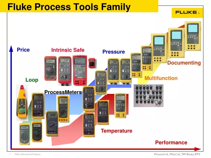
Fluke Process Tools Family. Price. Intrinsic Safe. Pressure. Documenting. Multifunction. Loop. ProcessMeters. Temperature. Performance. What is Calibration?. Calibration is the comparing of a measurement device ( an unknown) against an equal or better standard ( or reference )

E N D
Fluke Process Tools Family Price IntrinsicSafe Pressure Documenting Multifunction Loop ProcessMeters Temperature Performance
What is Calibration? • Calibration is the comparing of a measurement device ( an unknown) against an equal or better standard ( or reference ) • The measurements and specifications of both the standard and unknown are documented to promote Traceability • Traceability is an unbroken chain of comparison from the measurement being done to a recognized national, legal standard.
Traceability NIST • Unbroken chain of calibration measurements from an Instrument to National Standards • With documented proof of the chain of calibrations
Why Calibrate? Uniformity Quality Compliance
Why Calibrate? +1% A 0% B -1% 90 days 180 Days 270 days 1 Year
Benefits of Calibration • Calibration insures all independent processes are NOW working to the same set of standards • Calibration insures these processes STAYworking to the same set of standards • Calibration supports product quality and SAVESmoney
Quality and measurement • Cannon balls must the right size • Too small - fall short • Too large - don’t fit cannon • Not round - lose accuracy • Wrong weight - wrong trajectory • Without calibrated measurements, quality is uncertain
4-20 mA Process Control 4-20 mA Signal from Valve positioner ADC DAC Transmitter I to P Pneu. Supply Temperature Alarm Valve Pressure Alarm Switch Final Control Element Uniformity relies on calibrated Instruments
Why instruments change • All instruments and tools change with • Time • Temperature • Humidity • Environmental Exposure • Normal Use (Wear and Tear) • Abuse • No two instruments change in the same manner
Example of transmitter specifications Instrumentation performance can change because of many factors
Does your .1% transmitter really perform with only a .1% error? List Transmitter Specifications Specifications Transmitter A Transmitter B Upper Range Limit (URL) 300 inH O 300 inH O 2 2 Accuracy 0.2% of span 0.1% URL Basic Specs of .2% & .1% Temperature Effect Zero 0.5% of URL per 100°F Span 0.5% of span per 100°F 1 Total 1.0% of URL per 100°F Static Pressure Effect Zero 0.25% of URL per 2000psi 0.25% of URL per 2000psi Span 0.25% of reading per 1000psi 0.25% of span per 1000psi 1 Total Define Operating Conditions Calibrated Span 0 to 100 inH O 2 Expected Temperature Change 50 °F Expected Static Change 500 psig Expected Reading 75 inH O 2 Convert all of the errors into common terms: Specifications Transmitter A Transmitter B Accuracy 0.2% x 100 = ±0.2 in H O 0.1% x 300 = ±0.3 in H O 2 2 Temperature Effect Zero 0.5% x 300 x 50/100 = ±0.75 in H O 2 Span 0.5% x 100 x 50/100 = ±0.25 in H O 2 1 Total 0.75 + 0.25 = 1.0 H O 1.0% x 300 x 50/100 = ±1.5 inH O 2 2 Static Pressure Effect Zero 0.25% x 300 x 500/2000 = ±0.19 inH O 0.25% x 300 x 500/2000 = ±0.19 inH O 2 2 Give a Working Performance of 1% & 1.5% !! Span 0.25% x 75 x 500/1000 = ±0.094 inH O 0.25% x 100 x 500/1000 = ±0.12 inH O 2 2 1 Total 2 2 2 Calculate Total Probable Error (TPE = SQRT(A +B +C ...) Transmitter A Transmitter B 2 2 2 2 2 2 2 2 TPE SQRT((0.2) +(1.00) +(0.19) +(0.094) ) SQRT((0.3) +(1.5) +(0.19) +(0.12) ) =1.55% ±1.04% for 100 inH O span for 100 inH O span 2 2 Technical Comparison Courtesy Of Fisher Rosemount Application Information
What are Specifications? • A written description of an instruments performance in quantifiable terms • Apply to the population of instruments having the same model number • Are based on the performance statistics of a sufficiently large sample of instruments • Describe group performance parameters rather than that for a single , specific instrument.
Resolution • Resolution: The smallest change in quantity that can be detected or provided by an instrument. Example: Ideal
Error • Error: The difference between the indicated and ideal value of a measured quantity Error = Indicated - Ideal Example: Error Indicated Ideal
Precision • Precision: A measure of the consistency or repeatability of a series of measurements Example: Ideal
Accuracy • Accuracy: The degree of conformity of an indicated value to a recognized, accepted standard value, or ideal value Example: Ideal
Accuracy and Uncertainty • Accuracy and Uncertainty are complimentary • taken literally, Accuracy is defined as “exactness; correctness” • an Accuracy of 99.9% has an Uncertainty of .1% • Accuracy in measurements refers to the closeness of a measurement result to the true value. • Accuracy becomes “the largest error that will be allowed under specific operating conditions”. • “the accuracy is 1%” is intended to mean that the limits of inaccuracy are plus or minus 1% • Be aware of “% of full scale” verses “% of reading” • Be aware of Typical verse Worst Case specifications • Be aware of temperature range over which specification applies
Accuracy: Simple Calculations • Given a truck with 200 gallon gas tank where the gauge accuracy is 1% of full scale • Accuracy = 1% of full scale = plus or minus 2 gallons • reading of 100 gallons could be 102 or 98 gallons (2% off) • reading of 10 gallons could be 8 or 12 gallons (20% off) • Same truck, gauge accuracy is 1% of reading • Accuracy = 1% = plus or minus 1% of value read • reading of 100 gallons could be 101 or 99 gallons • reading of 10 gallons could be 10.1 or 9.9 gallons
Accuracy: Digital Meter Calculations • Absolute accuracy includes a ‘floor’ figure • expressed as “+ Y” range of digits or counts • “ +2 ” digits on a 100.0 reading could be a true value of : X% of input + Y digits 100.2 100.1 100.0 99.9 99.8
Accuracy: Fluke 787 Process Meter Measuring 4mA DC .05% + 2 Specification: 30mA Range (spec’d as % of reading) • Step 1: 4mA * .05% = 4mA * .0005 = .002mA or 2uA • Step 2: 30.000 mA range has .001mA resolution; • therefore “+2” counts = .002mA or 2uA Step 3: Total worst case deviations = .004mA Absolute Accuracy on 4mA = .004mA, or .001 or .1% Worst case limits between 4.004mA and 3.996mA
Accuracy: Fluke 787 Process Meter Measuring 20mA DC .05% + 2 Specification: 30mA Range (spec’d as % of reading) • Step 1: 20mA * .05% = 20mA * .0005 = .01mA or 10uA • Step 2: 30.000 mA range has .001mA resolution; • therefore “+2” counts = .002mA or 2uA Step 3: Total worst case deviations = .012mA Absolute Accuracy on 20mA = .012mA, or .0006 or .06% Worst case limits between 20.012mA and 19.988mA
Current loop devices • Transmitters • Temperature, pressure, flow, analytical • I to P, 4-20 mA input, 3-15 PSI output • Control Valves • PLC and DCS analog Inputs • Indicators • Controllers • Flow computers • Chart recorders • PLC: Programmable Logic Controller • DCS: Distributed Control System
Tools used to Troubleshoot and Calibrate Current Loop instruments used in industrial processes 2200 ºC What Loop Tools Do? Current Loop 4 to 20mA analog (2 wire) signal for communication between instruments, controllers, and indicators Instrumentation Transmitter SENSOR 2 2 5 2 span zero Controller PLC, DCS Indicator CONTROL ELEMENT
Sensor ZERO SPAN T-Type Thermocouple Transmitter 0 to 300 Deg C Applications: Typical Transmitter • Converts low level, non-linear signal to linear 4 - 20 mA • Millions in service, require service and calibration
Loop 24V Loop 24V Troubleshooting the 4-20 mA loop Temperature Transmitter Pressure Transmitter
Loop 24V Loop 24V Troubleshooting the 4-20 mA loop Don’t “Break the loop” In series, “Break the loop” Temperature Transmitter Pressure Transmitter
2200 ºC Loop Supply ZERO SPAN Fluke 789 Applications: Measure Loop Current • Fluke 789 measures external current • Current and % readout • 1 microamp resolution, high accuracy Sensor 4 to 20 mA Readout / Controller DCS / PLC / Recorder
Loop 24V Loop 24V Troubleshooting the 4-20 mA loop Temperature Transmitter Pressure Transmitter
Current to Pressure (I/P) 3-15 psi 4-20 mA Fluke 789 Applications: Source Current Signals • 789 outputs current • Current and % readout • 1 microamp resolution • 25% steps, course and fine • Ramp current
20 4 Stroke Valves • Fluke 789 outputs current • Ramp current • Step Current • Watch control element 4-20 mA
Loop 24V Loop 24V Troubleshooting the 4-20 mA loop Simulate a transmitter in a loop, regulate current Temperature Transmitter Pressure Transmitter
Sensor 2200 ºC Loop Supply ZERO SPAN Fluke 789 Applications:Simulate Transmitter Signals • 789 ‘throttles’ or controls current, acts like variable resistor • Current and % readout • 1 microamp resolution • 25% steps, course and fine, ramp 4 to 20 mA Readout / Controller DCS / PLC / Recorder
Loop 24V Loop 24V Troubleshooting the 4-20 mA loop 24.000 VDC Temperature Transmitter Pressure Transmitter
Loop 24V Loop 24V Troubleshooting the 4-20 mA loop Temperature Transmitter Pressure Transmitter
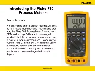
The Fluke 787 - The Premier DMM for Process Technicians • Professional Quality DMM • AC/DC volts - 1000 Volts • AC/DC Amps - 440mA (1A, < 30 sec) • Ohms • Continuity, Diode check • Frequency • Backlight • Safety - Cat III 1000V • 0.1% VDC, 0.05% mA Accuracy • 0-22 mA Current Source • 1 microAmp Resolution and Adjustment • Auto Ramping and Stepping
Dependable Fluke 787 • The Fluke 787 is a hit... • But customers asked for more • 24 volt loop supply • drive 1200 ohms in mA source • slower auto step • 5 volt ranging
The more powerful Fluke 789 • The Fluke 789 delivers all of that and more • 24 volt loop supply • drive 1200 ohms in mA source • slower auto step • 5 volt ranging • larger, brighter display • longer battery life • easier calibration; manual procedure • calibration seal • selectable 250 ohm HART resistor
Introducing the new: Fluke 771 mA Process Clamp Meter Innovative new approach to measuring mA loop signals • Measure mA signals without breaking the loop • Best in class mA measurement accuracy and resolution • Save time and money troubleshooting PLC analog I/O and process loops • Detachable clamp with extension cable • Dual display with both mA and % of span readouts • Measurement spotlight illuminates hard to see wires. Measure 4-20 mA signals without breaking the loop.
Troubleshoot and Commission Fluke 771 Applications Instrumentation, Automation and PLCs: • Transmitters • Valves, I/Ps, other 4-20 mA devices • Analog I/O • PLC Analog I/O • DCS Analog I/O • Building Automation and HVAC controls • Measure mA control signals on terminal blocks quickly • without shutting down the system
Cost Justification, Cost Savings • No need to lift a wire from a terminal (break the loop) to measure 4-20 mA • Not need to call a control room to override control of a process loop to breaking the loop • Confirm operation of analog I/O for a PLC or DCS without the need to verify at a display or break the loop
Fluke 771 Summary • Best in class mA accuracy and resolution • 0.2% and 0.01 mA • Unique value--cost payback proposition • Feature rich: • Measurement hold, extension cable, spotlight, backlight • Uniquely targeted to process/HVAC user needs • mA and percent of 4-20 mA span displays • Best accuracy at 4-20 mA measurements • Over ranges to 99.9 mA to support 10-50 mA applications Innovative new mA measurement tool