Download
1 / 26
290 likes | 470 Views
Visual servoing & Tracking using 2DOF helicopter: The results. Chayatat Ratanasawanya Min He May 13, 2010. Overview. Background information The goal Tasks involved in implementation Depth estimation Pitch & yaw correction angle calculation Image processing LQR controller

E N D
Visual servoing & Tracking using 2DOF helicopter:The results ChayatatRatanasawanya Min He May 13, 2010
Overview • Background information • The goal • Tasks involved in implementation • Depth estimation • Pitch & yaw correction angle calculation • Image processing • LQR controller • Experimental setup • Results • Data analysis • Conclusion • Questions/comments
Background • Visual servo (VS) control – the use of computer vision data to control the motion of a robot. • Relies on techniques from computer vision, image processing, and control theory. • Two camera configurations: • Eye-in-hand: camera is mounted on a robot manipulator or on a mobile robot. • Camera is fixed in the workspace
Background • The goal of visual servoing systems is to minimize the error defined by where s is visual feature vector s* is the desired visual feature vector • Design of s: • Consists of a set of features that are readily available in the image data (IBVS), or • Consists of a set of 3D parameters, which must be estimated from image measurements (PBVS)
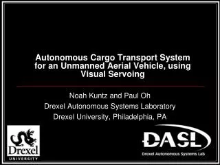
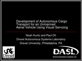
The goal • Use visual servoing techniques to make the 2DOF helicopter be able to track a constantly moving ping-pong ball. • Quanser 2DOF helicopter • A typical two-rotor helicopter model on a stand. • It pitches and yaws around a pivot point.
Implementation • Tasks involved: • Depth estimation • Pitch & yaw correction angles calculation • Image processing • LQR controller
Experimental setup • We did 4 experiments altogether: • 2 tests with the camera 25” from the wall • 2 tests with the camera moved further back
Depth estimation • Use the diameter of the ball in image to estimate the depth Actual ball diameter db=40mm Ball diameter on image, d Depth, Z Focal length f=268 pixel Center of projection (CoP)
Correction angle calculation l 1 Z Ball diameter on image, d ue 2 ue 2 1 Z f CoP r ψ Pivot point of the 2DOF helicopter
Correction angle calculation l 1 Z Ball diameter on image, d 2 ue Z f CoP r ψinc Pivot point of the 2DOF helicopter
LQR controller • A controller design technique that works with the state-space representation of a system. with weighting matrices Q and R, calculate • Same action as a PD or a PID controller. • It is a position-based, joint-level controller. It accepts desired pitch and yaw angles and brings the helicopter to those angles. • The desired angles are updated according to image processing result.
Result: Visual servoing test 1 Video from on-board camera
Result: Visual servoing test 2 Video from on-board camera
Result: Tracking Video from on-board camera
Data Analysis • Experiment 1 - Visual servoing • 2DOF helicopter is at position 1 (25” from background)
Data Analysis • Experiment 1 – visual servoing at position1
Data Analysis • Experiment 1 – visual servoing at position1
Data Analysis • Experiment 1 – visual servoing at position1 • Horizontal direction (Yaw) • overshoot = 9.53% • Settling time = 16.19s • Steady state error = 1 pixel • Vertical direction (Pitch) • overshoot = 2.75% • Settling time = 14.48s • Steady state error = 0.9 pixel
Data Analysis • Experiment 2 – tracking at position 1
Data Analysis • Experiment 3 – visual servoing at position 2 • The helicopter is moved further from the background
Data Analysis • Experiment 3 – visual servoing at position 2 • Horizontal direction (Yaw) • overshoot = 10% • Settling time = 17s • Steady state error = 1.4 pixel • Vertical direction (Pitch) • overshoot = 7.09% • Settling time = 5.75s • Steady state error = 0.4 pixel
Data Analysis • Experiment 4 – tracking at position 2
Conclusion • The implemented visual servoing algorithm is simple because the 2DOF helicopter is a very simple system. • Data shows that the 2DOF is able to “visual servo” the ball to the middle of the image frame. The LQR controller works better for the pitch than for the yaw: smaller overshoot and steady-state error.
Conclusion • It is able to track a constantly moving ping pong ball. The limitation is that the ball cannot move faster than 38.1cm/s. • The distance of the ball from the camera does not matter as seen in tracking when the ball moves closer to the camera. • The location of the 2DOF helicopter does not affect the performance of the system.
Thank you • Questions/comments are welcome