Download
1 / 31
540 likes | 1.38k Views
Microstructure Studies of Carbon-Carbon Composite Materials. Kei Yamamoto Purdue University Advisor: Prof. Alex King. Presentation Outline. Background information on Carbon-Carbon Composites Optical Microscopy images X-ray diffraction results SEM images Conclusions Future Work.

E N D
Microstructure Studies of Carbon-Carbon Composite Materials Kei Yamamoto Purdue University Advisor: Prof. Alex King
Presentation Outline • Background information on Carbon-Carbon Composites • Optical Microscopy images • X-ray diffraction results • SEM images • Conclusions • Future Work
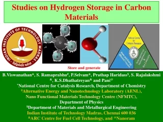
What are Carbon-Carbon Composites? • Amorphous carbon matrix composite • Carbon matrix reinforced by graphitic carbon fibers • First developed in 1958, but not intensively researched until the Space Shuttle Program (for insulation)
How are Carbon-Carbon composites made? • First carbon fibers are made by pyrolizing Poly-acrylo-nitrile (PAN) fibers • Pyrolized fibers then woven into the desired pattern • Spaces between the fibers are filled by Chemical Vapor Deposition (CVD) http://www.fibermaterialsinc.com/frSW.htm
Properties of Carbon-Carbon Composites • Outstanding durability at temperatures over 2000ºC • Low coefficient of thermal expansion • Great thermal shock resistance • High strength • Low weight • High melting point • Corrosion resistant • Expensive • Long time to manufacture (weeks to months)
Properties of Carbon-Carbon http://www.hitco.com/products/corrosion/chemical/index.html
Uses of Carbon-Carbon Composites http://www.fibermaterialsinc.com/frSW.htm • Aircraft, F-1 racing cars and train brakes • Space shuttle nose tip and leading edges • Rocket nozzles and tips http://www.futureshuttle.com/conference/ThermalProtectionSystem/Curry_73099.pdf http://www.fibermaterialsinc.com/frSW.htm
Original goals of my project • To determine how the microstructure of the carbon-carbon composites affect the properties of aircraft brakes • To find out the best methods to determine porosity and fiber alignment to be used as quality control tests
Optical Microscopy Sample 1:
Optical Microscopy Sample2:
Optical Microscopy Sample 3:
Microtome • Cuts thin slices (microns thick) of your specimen • Specimen must be soft Beem Capsule Microtome
SEM Images Sample 1:
SEM Images Sample 2:
SEM Images Sample 3:
SEM Images Sample 4:
Conclusions • Crystallinity of carbon fibers varies considerably between specimens • In samples 2, 3 and 4 the amorphous carbon matrix and carbon fibers are not well bound together, thus matrix is not providing any benefits to the structure • In sample 1 amorphous carbon matrix and carbon fibers are bound together but it is not inter-grown together, thus matrix is still not providing any benefits to the structure • Carbon was only deposited on the surface in one of the specimens: amorphous carbon nucleation is found only very rarely on the fiber surfaces in this specimen
Future Work • Improvement of the sectioning process to retain shell and core structure of carbon-carbon composite • Refine techniques for embedding the material • Develop a capacity for thin section specimens for transmitted light microscopy and TEM • Routine SEM and XRD • Relate results to processing the samples have been exposed to
Acknowledgements • Prof. Alex King • Indiana 21st Century fund • Honeywell