Download
1 / 30
300 likes | 429 Views
Structure of Computer Systems. Course 3 The Arithmetical and Logical Unit. ALU- Arithmetical and Logical Unit. Purpose: computes arithmetical and logical operations: arithmetical: basic operations: add, subtract, multiply, division, modulo

E N D
Structure of Computer Systems Course 3 The Arithmetical and Logical Unit
ALU- Arithmetical and Logical Unit • Purpose: computes arithmetical and logical operations: • arithmetical: • basic operations: add, subtract, multiply, division, modulo • special functions: exponential, logarithm, sine, cosine, tangent, atangent, etc. • logical: • AND, OR, NOT, inclusiveOR, exclusiceOR • Types of arithmetic units: • integer arithmetic • floating point arithmetic (e.g. Intel’s co-processor) • signal processing arithmetic (e.g. with saturation MMX) • parallel arithmetic (MMX - integer, SSE2- floating point)
Addition • most used operation • all the other arithmetic operations are based on addition: • subtract – adding the complement • multiply – repetitive adding • division – repetitive subtraction and adding • efficient implementation of adding operation: • influence directly all the other operations • efficiency: speed and cost (complexity)
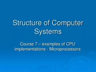
xi yi Ci-1 xi yi Ci One bit adder Ci-1 Si Si Ci Addition • Basic (full) adder unit – one bit adder • inputs: xi, yi, Ci • outputs: • Si = xiyi Ci • Ci = xiyi + (xi yi) Ci-1 • delay: 3* gate_delay
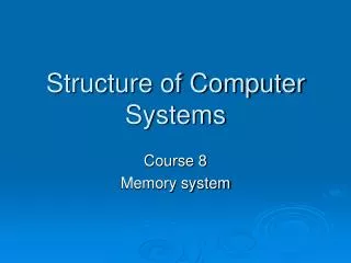
x1 y1 1 bit adder C0 x0 xn-1 X Y xn-2 y0 yn-1 yn-2 S1 Cn-1 C-1 Cn-2 Cn-3 1 bit adder 1 bit adder 1 bit adder n bit adder S0 Sn-1 Sn-2 S “n” bit adder with ripple carry • n bit adder = n * (1 bit full adder) • delay: n*3*gate_delay • example: • n=32; gate_delay = 10 ns (TTL gate) => • delay: 32*3*10ns ~= 1000 ns => fclk_max = 1/1000 ns = 106 =1MHz !!!
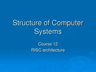
x1 x0 xn-1 xn-2 yn-1 yn-2 y1 y0 Add/Sub 1 bit adder C0 1 bit adder Cn-1 1 bit adder Cn-2 1 bit adder Cn-3 S1 S0 Sn-1 Sn-2 Subtract • subtract = adding with the second number’s 2th complement • n bit add and subtract: • Add/Sub = 0 => adding • Add/Sub = 1 => subtraction
Data Bus (D0-D15) 0 1 Sel MUX Clk Ld_A/ Control unit Instr. code Ld_B/ Amp. Temp Reg. A Reg. B Add/Sub Add&Sub Wr_m/ Sequence of steps for adding
Improving the AdderCarry Look-ahead Adder • Issue:the delay time of the carry • Solution: direct generation on carry => “Carry lookahead adder” Ci = xiyi + (xi yi) Ci-1= gi +pi*ci-1 where: gi – carry generator pi – carry propagator C0 = x0y0 + (x0y0)C-1 = g0 +p0*C-1 C1 = x1y1 + (x1y1)C0 = g1 +p1*C0 = g1 +p1*(g0 +p0*C-1)= g1 +p1g0 +p1p0C-1 C2 = x2y2 + (x2y2)C1 = g2 +p2*C1 = g2 +p2*[g1 +p1*(g0 +p0*C-1)] = = g2 +p2g1 +p2p1g0 +p2p1p0*C-1 ...... Ci =f(g0, g1, ... gi, p0, p1, ... pi, C-1) = f(x0, x1, ... xi, y0, y1, ... yi,C-1) Conclusion: Ci is obtained directly by combining ONLY input signals Drawbacks: - the circuit’s complexity grows exponentially with the number of bits (n) - it requires gates with a lot of input signals - delayideal = 2*gate_delay
xn-1 yn-1 x0 y0 x1 y1 C-1 1 bit adder 1 bit adder 1 bit adder Cn-1 pn-1 gn-1 C1 p1 g1 C0 p0 g0 Carry Look-ahead Unit (CLU) S0 S1 Sn-1 Carry Look-ahead Adder - CLU • generates a result in a shorter time • CLU is feasible for 4 bits – the gate inputs’ number is limited • it can be extended putting together 4 bit adders
Carry Look-ahead Adder • extension from 4 bits to 16 bits • Generators and propagators for blocks of bits from “i” to “k”: • Group generategi,k • Group propagatepi,k • For a block of 4 bits: G0,3 = g3 + p3 g2 + p3 p2 g1 + p3 p2p1 g0 P0,3 = p3 p2p1 p0 • Using this notation we obtain block caries C3, C7, C11,C15 C3 = G0,3 + P0,3C-1C7 = G4,7 + P4,7C3= G4,7 + P4,7(G0,3 + P0,3C-1)
X0-3 Y0-3 X0-3 Y0-3 X0-3 Y0-3 X0-3 Y0-3 C15 C-1 4 bit adder C3 4 bit adder 4 bit adder C11 C7 4 bit adder p0,3 p0,3 p0,3 p0,3 g0,3 g0,3 g0,3 g0,3 C3 p3 g3 C2 p2 g2 C1 p1 g1 C0 p0 g0 4 bit carry look-ahead unit S0-3 S0-3 S0-3 S0-3 Carry Look-ahead Adder • 16 bit carry look-ahead adder made of: • 4 units of 4 bit carry look-ahead adders • one 4 bit carry look-ahead unit
Y7,4 X7,4 Y3,0 X3,0 1 0 4 bit adder 4 bit adder 4 bit adder C3 1 0 MUX S3,0 C7,S7,4 Carry select adder • Extra hardware to speed-up the adding • Avoids complex carry look-ahead unit
Serial adder • Adding two sequences of bits with a 1 bit adder An-1 ….A2 A1 A0 Ai shift entry Si 1 bit adder Sn-1 ….S2 S1 S0 Bi Ci shift entry Ci-1 Bn-1 ….B2 B1 B0 Q D clk Clk
X3,0 Y3,0 S3 S2 S1 S0 C Corr 0 0 0 0 0 0 • 89+ • 42 • CB+ correction • 66 • 131 4 bits adder 1 0 0 1 0 0 1 0 1 0 0 1 1 0 1 1 0 1 S’3,0 1 1 0 0 0 1 0 0 1 1 0 1 0 1 1 1 1 0 0 1 4 bits adder 1 1 1 1 0 1 x x x x 1 1 S3,0 BCD adder • adding numbers in BCD –(binary coded decimal) representation • a correction is needed: • if the figure is not a decimal • If a carry is generated to the next group of 4 bits (to the next decimal figure) • solution: adding 6 (both cases) • Example:
Multiplication • Multiply = repeated adding Modified multiply: 00000000 Acumulator (AC) “0” → 0000000 0 shift right “1” → 1100 adding 0001100 0 partial product 000110 00 shift right. “0” → 00011 000 shift right “1” → 1100 adding 1111 000 final product Solution: shift the partial result to the right and put the product in the same place Advantages: - we need just an n bits adder - partial products in the same place 1100 * 12 * 1010 10 0000 1100 0000 1100 1111000 = 78H = 120 Issues: - we need a 2n bits adder - partial products must be placed in different positions
BS AS An-1 Bn-1 . . . . . . A1 B1 A0 B0 Multiplication X (n+1) Q S Q n-1 . . . Q1 Q0 Y Scriere Test Shift Command unit Shift Clear Write Write
Multiply algorithm • Write the operands in registers (B ← X, Q ← Y), clear accumulator (A ← 0) • Complement the negative numbers • Test Q0 • If Q0 = 0, shift right A and Q • If Q0 = 1, add A = B + A and shift right A and Q • Go to step 3 until Yn-1 arrives in Q0. No shift is needed after the last step • AS = BS + QS • If AS = 1 complement the result
Multiply with Booth algorithm • Improvements: • Multiply numbers in 2th complement; no initial and final complementation are needed • For long sequences of 0s and 1s only shift operations are needed: • For 0s – it is obvious from the previous method • For a sequence of 1s: • Examples: 1111 = 10000 -1; 11.1111 = 100.000 – 1 • A sequence of 1s can be changed into a sequence of 0s • Only transitions from 0 to 1 or 1 to 0 needs adding or subtract operations as follows: • If two consecutive bits in the second operand are: • 0 and 0 - shift the partial result to the right • 0 and 1 – add second operand and shift the partial result to the right • 1 and 0 – subtract the second operand and shift the partial result to the right • 1 and 1 - shift the partial result to the right
Division • Multiple solutions: • Compare and subtract • Hard to compare on different positions • Subtract and restore the partial result (if necessary) • Subtract the second operand from the most significant part of the first operand and • If the result is positive than its ok (quotient gets a 1), • Else restore the result by adding back the second operand (quotient gets a 0) • Drawback: some steps require 2 arithmetical operations (subtract and adding) • Subtract without restoring the partial result • try to subtract B from the partial rest R’=R-B • If a wrong subtraction was made in the previous step the correction is made in the next step by adding the second operand instead of subtracting it • With correction: ((R-B) +B)*2 - B = R*2 - B ; A shifted one position to the left • Without correction (R – B)*2 + B = R*2 – B • Advantage: in a step at most one subtraction or adding is needed
X AS BS An-1 Bn-1 . . . . . . B1 A1 B0 A0 Q S Q n-1 . . . Q1 Q0 Adding, Subtraction Command unit Add / Sub Y Division circuit for the second method – restoring the partial result
Division algorithm – with restoring the partial result • Load first operand in A and Q; Load second operand in B • Write AS + BSin QS. • If AS = 1, complement A, Q • If BS = 1, complement B • Tests: • A ≥ B, overflow • B = 0, division with 0 • A = 0 and Q < B, rezult = 0 • Shift A, Q to the left and put 0 in Q0 • Subtract B from A and put the result in A. • if AS = 0 (positive rest) , shift A, Q to the left and put 1 in Q0 • else (AS = 1 negative rest), add B to A, shift A, Q to the left and put 0in Q0 • Go to step 5 n times • Rounding the result. If A ≥ B, add 1 to the Qth complement • If QS = 1 complement register Q
Multiply with look-up tables • Principle: all the results are pre-computed and memorized in a non-volatile memory • Multiply is a simple reading from the memory • Operands form the address of the location where the result is stored • Problem: the dimension of the memory must be 22n • Examples: • 8*8 bits => 16 address lines => 216 = 64KB • 16*16 bits => 32 address lines => 232 = 4GB (TOO MUCH) • Solution: • Multiply 8*8 bits in multiple steps to obtain multiply on 16, 32 or 64 bits • Example: X= X15,8 X7,0 Y= Y15,8 Y7,0 P = X*Y = X7,0*Y7,0 + X15,8*Y7,0 *28 + X7,0*Y15,8 *28 + X15,8*Y15,8 *216 Observation: multiplies with 28 and 216 are achieved by placing the result in a proper binary position; also the first and the last partial products may be combined in a single 32 bit register with no adding required
X15,8 X15,0 MUX X7,0*Y7,0 X15,8*Y7,0 X7,0*Y15,8 X7,0 Memory Look-up table A15,0 D15,0 Y15,8 MUX Y15,0 X15,8*Y15,8 Y7,0 MUX Control unit Adder Accumulator Multiply with look-up table WrX WrY Sel1 Sel0 WrP1,2 WrP0 WrP3 Sel2 WrAcc
Multiply with look-up table • Multiply with look-up table requires only 7 steps instead of 16-20 • it can be further optimized
Arithmetical operations in floating point (FP) representation • Floating point representation of a number: • Used in case of very big or very small numbers • 3 fields for representation: • Sign • Exponent – magnitude of the number • Mantissa – some significant figures (digits) of the number • IT IS NOT THE REPRESENTATION OF REAL NUMBERS from mathematics !!!!! • A lots of anomalies and precision problems: • Operating with numbers having different magnitudes may generate errors caused by rounding: • M+m-M = 0 ; M-M+m = m • Number with decimal parts, in most cases have no precise FP representation • Example: 0.3 has no precise representation in floating point
X Shift right Inc/Dec S exponent mantissa < Control unit = Compare Add & subtract > exponent S mantissa Inc/Dec Shift right Add/Sub Y Floating point adder/ subtracter
Adding floating point numbers • Load the operands • Compare exponents(5 cases): ex = ey, add mantissas and copy the exponent ex > eyand (ex – ey) < number of bits in the mantissa, than the my mantissa is aligned by shifting it with ex-ey positions to the right; ex >> eyand (ex – ey) ≥ number of bits in the mantissa, than X is copied in the result (Y is too small); go to step 4 ex < eyand (ey – ex) < number of bits in the mantissa, than the mxmantissa is aligned by shifting it with ey-ex positions to the right; than mantissas are added ex << eyand (ey – ex) ≥ number of bits in the mantissa, than Y is copied in the result (X is too small); go to step 4 • Add mantissas • Realign the result if necessary. Shift the resulting mantissa to the right or to the left until the integer part is 0 and the first bit after the decimal point is 1; in the same time increment or decrement the exponent in accordance with the shifting operation
Multiply and division in floating point representation • Multiply: • Add the exponents • Multiply the mantissas • Adjust the result (shift mantissa to the left and decrement the exponent if necessary) • Division: • Subtract the exponents • Divide the mantissas • Adjust the result (if necessary)
R2 R1 Ui Ue Add and Subtract with saturation • Idea: if there is an overflow or underflow after an adding or subtraction the result should be the maximum or the minimum possible value • example: • unsigned 8 bit representation Normal adding (wraparound)With saturation 80h+90h = 10h (error, overflow) 80h+90h = FFh (maximum value) 80h-90h = F0h (underflow) 80h-90h = 00h (minimum value) • signed (2th complement) 8 bit representation Normal adding (wraparound)With saturation 70h+20h = 90h (error, negative) 70h+20h = 7Fh (maximum value) 80h-20h = 60h (error, positive) 80h-20h = 80h (minimum value) (-128-32 = 96) • Used in case of: • signal processing • multimedia processing • Typical signal processing operation: amplification Ue = Ui *A Supply: +10V;-10V, Ui=0.05 V; A=100 =>Ue = 5V Ui=1.00 V; A=100 =>Ue = 10V !!! – upper saturation
X7,0 Y7,0 Add/Sub Add&Sub Carry FF 00 S1 3 2 1 0 S0 MUX S7,0 Add and Subtract with saturation • Add and subtract with saturation for unsigned 8 bit representation • the result is selected with a multiplexer: • Carry (C) = 0 => result correct • C=1 and adding => overflow, result=FFh • C=1 and subtract => underflow, result=00h • homework: do it for 2th complement Add/Sub Add/Sub C C