Download
1 / 44
440 likes | 615 Views
ANALYSIS AND DESIGN OF CONVERTERS IN MATLAB. FINAL PROJECT THESIS PRESENTATION RODRIGO LORENTE SANJURJO THESSALONIKI, Mar.12, 2010. OBJETIVES. Give a general idea about the importance of the converters (ADCs). Help to understand the characteristics and behavior of an ADC.

E N D
ANALYSIS AND DESIGN OF CONVERTERS IN MATLAB FINAL PROJECT THESIS PRESENTATION RODRIGO LORENTE SANJURJO THESSALONIKI, Mar.12, 2010
OBJETIVES • Give a general idea about the importance of the converters (ADCs). • Help to understand the characteristics and behavior of an ADC. • Analysis of non-idealities. • Study the effects of real converters in bigger circuits.
INTRODUCTION • It is said that “the world is becoming digital”. • Evolution: Originally mechanical -> Electrical -> Solid-State. • Optimization of resources and performance. • E.g.: Audio.
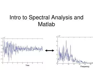
THEORY • The analog-to-digital conversion consists in the transformation of analog signals into digital ones. • A digital signal have discrete time and amplitude. • An analog signal is one whose amplitude can (in principle) take any value, which does not mean that it have infinite precision.
Advan & Disad. of digitizing a signal Advantages Disadvantages • Easy reconstruction when attenuated or disturbed. • Systems of detection/correction of errors. • Easy signal processing. • Multigeneration infinitely without quality loss. • Data compression techniques. • It needs the conversion and the decoding. • If not enough quantization levels, it decreases SNR. • It is necessary a low-pass filter to avoid aliasing (also during the reconstruction).
Concepts • Resolution: number of discrete values in what the entire range of analog values can be transformed. Limited by the SNR. • Sampling rate: speed at which the analog signal is sampled. • Signal to Noise Ratio (SNR) • Signal to Noise and Distortion (SINAD) • Effective Number of Bits (ENOB) • Spurious-Free Dynamic Range (SFDR)
Concepts • Quantization Error: due to the finite resolution of an ADC. • Offset Error • Full-Scale Error • Gain Error • Non-linearity: DNL and INL • Missing Codes • …
Architectures • Direct Conversion ADC or Flash ADC: bank of comparators in parallel, the fastest, limited resolution, exponential growth.
Architectures • Successive-Approximation ADC: it constantly compares the value with different references until the best approximation is achieved.
Architectures • Wilkinson ADC: it compares the input with the voltage of a load capacitor that discharges linearly when both voltages are equal, generating a pulse with the duration of the discharge which operates a logic gate that allows the pass of a pulse train. • Sigma-Delta ADC (∑-∆): it uses oversampling to limit the quantization noise to the bandwidth of the signal. • Pipeline ADC • Integrating ADC (dual-slope or multi-slope) • Ramp-compare ADC • Time-interleaved ADC • …
HISTORY • The first noticed kind of converter was in Turkey at 18th century. An “8-bit DAC” to measure water. • Communications field, the main force behind the development of electronic data converters. • Need for multiplexing: Pulse Code Modulation (PCM), first time in a patent of Paul M. Rainey, then developed by Alec Harley Reeves, covering the counter-based design for 5-bit ADCs and DACs
HISTORY • At the beginning they used vacuum tube technology: expensive, bulky and high energy consumption. • Migration to transistor (1950s-1960s). 1978 1966 1954
HISTORY • Three different technologies: • Monolithic • Modular • Hybrid • Until 1990s predominance of modular and hybrid.
HISTORY • Present and future: • Converter closer to the “original signal”. • Integrate converters with other functions. • “Performance saturation”. • Very high level of transistor density. • Digital post-processing to compensate analog non-idealities.
CODE • Steps: • Thresholds of decision. • Comparison matrices. • Calculation of the digital output. • Calculation of non-idealities. • Graphical representation.
Thresholds of decision • Initially all the thresholds correspond to the ones of the ideal case (each multiple value of LSB).
Thresholds of decision • Two parameters: • Steps • Slopes • Two operation modes: • Single value • Vector of values
Steps steps = -0.5 steps = [0 -0.7 0 -0.5 0.5 0 0.7 0]
Slopes slopes = 2 slopes = [1.2 1 1.5 1 1 0.5 1 1]
Thresholds of decision % ADC's real transfer function converter = zeros(2,2^nbits); % Thresholds of conversion slope_steps = ((ones(1,2^nbits)./slopes)-1)*triu(ones(2^nbits,2^nbits)); converter(1,:) = ((1:2^nbits)+slope_steps+steps)*vlsb; % Digital output values converter(2,:) = (1:2^nbits)-1;
Comparison matrices • With the thresholds we generate two matrices • Reference matrix • Matrix with the input information
Comparison matrices % Auxiliary (2^nbits)x(length(vin)) matrix with the square of each digital % value in the columns aux = vin*0+1; % Weight up the new matrix with the reference voltage and the number of % bits aux = (converter(1,:)'.^2*aux); % Weight up the input and compare it with the auxiliary matrix conversion = converter(1,:)'*(vin*vref/2);
Calculation of the digital output conversion = conversion>aux; % After fixing the problem of bubbles the output will be the number of ones % in each column out = max(((1:2^nbits)'*ones(1,length(conversion))).*conversion); % Limit maximum output value out(out>2^nbits-1) = 2^nbits-1;
Calculation of the digital output • Two problems: • Negative Thresholds • Bubbles
Negative Thresholds • R is the highest negative or zero threshold • Avoid problems % Readjust negative thresholds R = find(converter(1,:)<=0,1,'last'); converter(1,1:R)=0;
Negative Thresholds • E.g.: R=2 • The problem are the outputs equal to zero % Compensation of the 0s for non-positive thresholds if R>0 out(out==0) = R; end
Bubbles • Caused by Missing Codes • Common in real converters
Bubbles • E.g.: • It does not affect thanks to the implementation. • Alternative code that finds the positions of the bubbles
Calculation of non-idealities • Best linear approximation. • Offset Error • Full-Scale Error • Gain Error • DNL • INL % ADC's transfer function's linear interpolation approxFunction = polyfit([steps(1) converter(1,1:end-1)/vlsb],converter(2,:),1); approxConverter = (converter(2,:)-approxFunction(2))*vlsb/approxFunction(1);
Calculation of non-idealities • It uses all the values to calculate the non-idealities. • Results in LSB units. % Output info offset = approxConverter(1)/vlsb; FSError = (idealConverter(end-1)-approxConverter(end))/vlsb; GError = FSError+offset; aux_inl = converter(1,1)-vlsb/slopes(1); % INL Adjustment INL = abs(approxConverter-[aux_inl converter(1,1:end-1)])/vlsb; DNL = ([converter(1,1:end-1) vref]-[0 converter(1,1:end-1)])/vlsb-1; DNL(DNL<=-1) = 0; % DNL Adjustment
Graphical representation • It is only represented the range between 0 and • Two options: % Plotting if strcmp(plotting,'full') ADCplotting(vin,out,nbits,vref,idealConverter,converter,approxConverter,vlsb,slopes(1)); elseif strcmp(plotting,'simple') ADCplottingSimple(nbits,vref,converter,vlsb); else disp('Wrong plotting input value'); end
Graphical representation % Number of points in the plot voltPoints = 2^14; converterRep = zeros(1,voltPoints); ---------------------------------------------------------- % Representation of the ADC transfer function scaling = voltPoints/vref; scaledConverter = converter(1,:)*scaling; scaledConverter(scaledConverter<0) = 0; for i = 2:2^nbits+1 converterRep(round(scaledConverter(i-1))+1:end) = i-1; end converterRep(converterRep>2^nbits-1) = 2^nbits-1;
EXAMPLES • Ideal 3-bit converter
EXAMPLES • steps = 0.75 & slopes = 1.4
EXAMPLES • steps = [0 0 0.3 0.5 -0.3 0.4 0.3 0]
EXAMPLES • steps = [0 0.2 0.2 0.8 -0.5 0.7 0 0]
EXAMPLES • steps = [1 1.3 1.5 2 2.5 2.7 4 0]
EXAMPLES • steps = [0 0.3 0.5 0 0 -0.2 0 0] & slopes = [1.5 1 1 0.8 0.8 2 2 1]