Download
1 / 7
70 likes | 203 Views
Level-1 Trigger Commissioning Status. A.Somov Jefferson Lab Collaboration Meeting, May 10, 2010. Trigger Commissioning and Monitoring Tools.

E N D
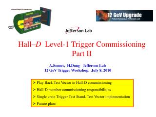
Level-1 Trigger Commissioning Status A.Somov Jefferson Lab Collaboration Meeting, May 10, 2010
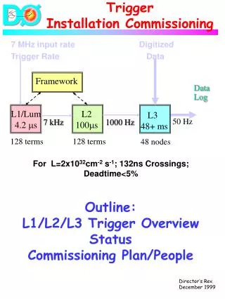
Trigger Commissioning and Monitoring Tools Level 1 Trigger Commissioning Status, GlueX Collaboration Meeting, May 10, 2010 2 • GlueX Level-1 trigger group responsibilities are to commission the trigger electronics and provide tools for monitoring the trigger performance. • Main tools: • •Test Vector • Trigger monitors Test Vector: •Check performance of the electronic boards (synchronization, code loaded to FPGAs…) and calibration constants. • Verify the trigger algorithm. • Will be performed during the trigger commissioning phase and before taking the data. Implementation: • Write predefined signal shapes to the FADC250’s FPGA memory. • Run the trigger hardware. • Compare hardware output with the MC predictions. Trigger Monitors: • Perform online monitoring of the trigger rates, occupancies, … during data taking • Will be implemented as scalers residing inside FPGAs.
Test Vector Implementation Level 1 Trigger Commissioning Status, GlueX Collaboration Meeting, May 10, 2010 3 Hai Dong Ed Jastrzembski David Abbott Ben Rayado Alex Somov Play Back TD TI Trigger FADC • • • 16 ch SD SD • • • 1 - 16 FADC CTP SSP TS GTP • • • 1 - 8 FADC SSP • • • 16 ch • Load FADC amplitudes of signal pulses to FPGA’s memory. • Trigger Supervisor initiates processing of the samples through the trigger hardware. Play Back signal will be delivered to the FADC through one of the trigger lines.
Play Back Mode: FADC pulse in the memory 16 x 4 ns = 64 ns (currently) play back pulse Level 1 Trigger Commissioning Status, GlueX Collaboration Meeting, May 10, 2010 4 Current version of FADC250 Trig from TI (one line for play back) Load Samples to Memory VMEbus Altera FPGA Play Back FIFO LX25 Self Trigger CTP FX20 LX25 FIFO • Load amplitudes of signal pulses (samples) to FPGA memory. • Play Back pulse width defines how many samples to process. • Trigger from TI initiates the VME readout (trigger can also be initiated by FX20 – self trigger mode)
Trigger Test Stand ROCK TI FADC Trig OUT Trig IN VME Trig IN Play Back - CODA - Load Samples Discriminator Pulse Generator Trigger Delay Level 1 Trigger Commissioning Status, GlueX Collaboration Meeting, May 10, 2010 5 • Maximum width of a signal pulse loaded to the memory: 16 x 4 ns. The same pulse shape is • loaded to all 16 channels. • Play Back signal is send to FADC through the VME P2 bus. • Use external trigger. TI initiates trigger interrupt. • FADC is operated in the “Window Raw Data” mode (read out specified number of samples). • Other readout modes have been checked as well (Pulse Raw Data, Pulse Integral).
Trigger Test Stand Level 1 Trigger Commissioning Status, GlueX Collaboration Meeting, May 10, 2010 6 FADC in the Window Raw Data mode • Load 11 amplitudes (samples) into • FADC memory. • The Play Back pulse width: ~ 70 ns. • The same pulse shape for all 16 channels. • Some work is needed to be able to load • different pulse shapes into different FADC • channels. Loaded Pulse Readout Window Play Back pulse
Summary / Future Plans Level 1 Trigger Commissioning Status, GlueX Collaboration Meeting, May 10, 2010 7 • We have started preparing for the Level-1 Trigger commissioning. • We received a lot of support/help from the Fast Trigger Electronics and DAQ groups. • Next Steps: • Finish with implementation of the “Play Back” mode – should be able to write • different samples to the16 FADC channels. • We are on the way to the 2 crate test stand. • - The new TI prototype and the new FADC version will be ready by the fall of 2010. • - DAQ official software is under development.