Download
1 / 19
190 likes | 347 Views
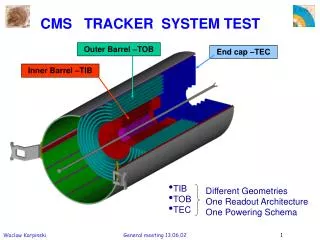
CMS Tracker Hardware Alignment. A.Ostaptchouk, RWTH-Aachen. Goals of TK hardware alignment Concept General layout Internal TK alignment External TK alignment (LINK) Hardware Conclusions. Goals of Hardware Alignment. External alignment: 100 m measurement of

E N D
CMS Tracker Hardware Alignment A.Ostaptchouk, RWTH-Aachen Goals of TK hardware alignment Concept General layout Internal TK alignment External TK alignment (LINK) Hardware Conclusions Workshop on b/tau Physics at LHC, Helsinki
Goals of Hardware Alignment External alignment: 100 mmeasurement of TK position w.r.t. MS 20 radmeasurement of TK orientation w.r.t. gravity both for joint TK+MS track fit Internal alignment: 100 mmeasurement of Si-module relative positions for track pattern recognition (recent H.Voss and B.Schwering results: 1000 m ! t.b.c.) 10 mmonitoring of Si-module positions stability for track parameter reconstruction Workshop on b/tau Physics at LHC, Helsinki
Concept of Hardware Alignment 1. No dedicated optical sensors Collimated laser beams with ~ 1060 nm produce signals directly in the TK Si-modules 2. No external reference structures All the elements of the alignment system are mounteddirectly on the TK parts 3. No precise positioning or aiming of beam collimators Number of measurements redundant enough to reconstruct detector positions without knowledge of laser beam initial parameters 4. Minimal impact on the TK layout and production technology The effected tracker parts are as uniform as possible Workshop on b/tau Physics at LHC, Helsinki
General Layout of Alignment System External alignment: six Ray 1 beams per TEC align TK w.r.t. MS Internal alignment: eight Ray 2 and eight Ray 3 beams per TEC align forward wheels, monitor 50% of petals eight Ray 4 beams align end-caps and barrels w.r.t. each other Workshop on b/tau Physics at LHC, Helsinki
Internal Alignment Implementation Laser beams through End-Caps holes in supports (petals, wheels) holes in back-side metallisation of Si-sensors (2500/24000) Laser beams through Barrels structure gaps in TOB inner shell alignment tubes inside these gaps fixed on TOB support discs Workshop on b/tau Physics at LHC, Helsinki
Internal Alignment Simulation Track residuals in End-Caps TEC: before applying alignment corrections RMS = 1.1 mm TEC: after applying alignment corrections RMS = 27 m Track residuals in Barrels TOB: after applying alignment corrections RMS = 49 m TIB: after applying alignment corrections RMS = 85 m Workshop on b/tau Physics at LHC, Helsinki
External Alignment Concept Concept of External Alignment System position of TK w.r.t. MS is determined by precise measurement of continuous laser beam positions inside TK and MS (LINK) On TK side it requires: 2D-sensors on TEC petals periscopes inside TEC back-disc orientation of TK w.r.t. gravity is determined by precise measurement of TEC back-disc orientation w.r.t. TEC wheels and gravity It requires back-disc instrumentation with Si-modules at radius of ray 2 and tiltmeters Workshop on b/tau Physics at LHC, Helsinki
Instrumented TEC back-disc External Alignment Elements Periscope mounted inside TEC back-disc 2D-sensor made of two Si-modules Workshop on b/tau Physics at LHC, Helsinki
External Alignment Simulation • TK-MSpos- precision of TK position w.r.t. MS • is defined by measurements of 6 laser • beams (ray #1) inside the TK volume: • r-positions of laser beams w.r.t. TK • r 20 m • -orientations of laser beams w.r.t. TK • 20 rad • (characteristic distance between TK and MS • L 5 m ) • TK-MSpos = r L100 m • TK-Gori- precision of TK orientation w.r.t. gravity • is determined by two independent factors: • back-disc orientation w.r.t. TEC • (measured by 8 laser beams, ray #2) • BD-TEC 10 rad • back-disc orientation w.r.t. gravity • (measured by 4 tiltmeters, requires their • calibration w.r.t. back-disc fiducials) • BD-G 10 rad • TK-Gori = BD-TEC BD-G 20 rad Workshop on b/tau Physics at LHC, Helsinki
Hardware:Experience from AMS-1 Workshop on b/tau Physics at LHC, Helsinki
Hardware:Experience from AMS-1 Si-module transparency (@ = 1064 nm)is about20 – 25 % Beam spotposition resolutionis better than10 m Workshop on b/tau Physics at LHC, Helsinki
Hardware 1D Si-Modules (Ray 2&3) 1D Si-modules for Ray 2&3 are the standard Si-modules of the TEC Rings 6&4 (both sides polished plus hole) Workshop on b/tau Physics at LHC, Helsinki
Status of LINK Elements 2D Si-Modules (Ray 1) 2D Si-modules are made out of two standard Si-modules from Ring 1 & Ring 2 (wafers W1 & W2) Workshop on b/tau Physics at LHC, Helsinki
Hardware Optical Wafers Production of optical wafers: Additional alignment wafers are included to the general order for Hamamatsu The company will polish their both sides and will produce holes in metallisation Prototypes will be delievered in July 2002 If they are OK (transparency, electrical properties), all the optical wafers – in Fall 2002 Tableof optical wafers LINK wafers Internal alignment wafers Workshop on b/tau Physics at LHC, Helsinki
Status of LINK Elements Periscopes Periscope mounting scheme: 3 very hard balls 2 CFC platforms 3 hardened Al inserts Workshop on b/tau Physics at LHC, Helsinki
Status of LINK Elements Periscopes Two options for the periscope design: Hollow CFC body with mirrors glued on it (Aachen) Single piece of quartz with mirror coated edges (Spain) Requirements for the periscope mounting/housing: Reproducibility: position 20 m orientation 100 rad Cold-warm transition: inside TK volume -10o C outside TK volume +20o C Workshop on b/tau Physics at LHC, Helsinki
Status of LINK Elements Tiltmeters Current choice: Wendor: Applied Geomechanics Serie: 756 (Mid-Range) Total range: 10 degrees Resolution: 1 rad Repetability: 2 rad Environmental: -25o C to +70o C, 0 to 100% hum. Sensors: 2 tilt , 1 temp Dimensions: 41x51x25 mm3 Workshop on b/tau Physics at LHC, Helsinki
Test Plans Test of Optical Si-Modules Workshop on b/tau Physics at LHC, Helsinki
Test Plans Test of Periscopes Workshop on b/tau Physics at LHC, Helsinki