Download
1 / 20
200 likes | 325 Views
Science Operations Center (SOC) Mission PDR Tim Quinn University of California - Berkeley. Overview. Science Operations Center Requirements Responsibilities Data Flow Data Products Data Access Data Analysis Software Data Archiving and Distribution Instrument Operations. Requirements.

E N D
Science Operations Center (SOC) • Mission PDR • Tim Quinn • University of California - Berkeley
Overview • Science Operations Center • Requirements • Responsibilities • Data Flow • Data Products • Data Access • Data Analysis Software • Data Archiving and Distribution • Instrument Operations
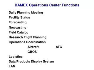
Responsibilities • Science Operation Center (SOC) is co-located with the MOC and is responsible for: • Instrument Data Collection • Data Processing and Product Generation • Data Validation • Data Distribution and Archiving • Instrument Operations Planning
Data Flow • Data Sources Include: • (5) Probe Instrument Complements which include • FGM • ESA • SST • SCM • EFI • (20) Ground Based Observatories • All Sky Imagers (ASI) • Ground Magnetometers (GMAG) • (10) E/PO GMAGS
Data Flow • Probe downlinks VC0-VC3 to ground station • Station routes VC0 and VC2 to MOC/ITOS • VC0 = Real-time Health & Safety • VC2 = Real-time Science Data • ITOS performs telemetry limit checking • VC1 and VC3 are routed to files at the ground station • VC1 = Stored Health and Safety • VC3 = Stored Science Data (480 – 640 Mbits)
Data Flow • At Approximately LOS+1Hr, file transfer begins • VC1 is FTP’d to MOC/ITOS which performs • telemetry limit checks • VC1 and VC3 are transferred to SOC
Data Flow • Reception of VC1 and VC3 files initiates Level Zero Processing • Data sorted by packet Application ID (AppID) • Packets are time-sorted if necessary • Data quality checks and statistics harvesting performed • Packets are mapped to a single 24 hour data file covering • 0000 GMT – 2359 GMT • 24 hour data file feeds CDF production process
Data Flow • Creation or update of a 24 hour data file or orbit data • initiates Common Data Format (CDF) file production • IDL based software using NSSDC CDF • libraries • Orbit data incorporated from products • supplied by Flight Dynamics Center (FDC) • CDF file covers same time period as 24 hour • LZP file • CDF file fed into Overview and Summary • plot production process
Data Flow • Creation or update to a 24 hour CDF file initiates • Science Overview Plot generation • Plots contain more detailed science and state • of health data • Operations scientist reviews plots to validate • instrument operation and calibration files
Data Flow • Creation or update of a CDF, calibration, • ASI, or GMAG file will initiate Summary Plot • Production • Associated data CDF available • Plots include: • Keograms (GBO Image Data) • Auroral Electrojet Indices (GBO GMAG Data) • E/PO GMAG Data • P1-P5 data • Combined Plot
Data Products • 24 hour instrument data Common Data Format (CDF) files • Instrument data calibration files • 30 Gbytes/year/probe (orbit/day) • Overview and summary data plots • Summary data in CDF format also • Summary data displays probe and ground based data • GBO data and calibration files • All Sky Imager (ASI) • 62 Gbytes/year/station • Ground Magnetometer (GMAG) • 757 Mbytes/year/station • E/PO GMAG data and calibration files • 757 Mbytes/year/station
Data Access • File Search Tool • Part of UCB Data Analysis Software Package • Local and remote access to all data • Search by probe, GBO site, E/PO GMAG site, and date • Web Interface • Instrument data CDF files • Summary data CDF files and plots • GBO data • E/PO GMAG data
Data Analysis Software • UCB will produce, maintain, and distribute a Data Analysis Software package to Co-I’s and general public (via website) • For instrument data, software exists in the form of an extensive library of IDL routines and the Science Analysis Tool (SDT) • Single probe analysis software (FAST, WIND) • Multi-point analysis software (ISTP, CLUSTER II) • Ancillary data software • Event modeling • For ASI/GMAG, tools (IDL routines) already exist for accessing, evaluating, and comparing ground observatory data with space-borne measurements (Adopted from existing NORSTAR and CANOPUS ground networks) • Software training sessions planned
Data Archiving and Distribution • Archiving • The following data and products will be permanently archived on disk drives and DVD storage • VC1 and VC3 files from the ground stations • 24 hour LZP files • 24 hour instrument CDF files • GBO data • E/PO GMAG data • Distribution • DVD’s containing 24 hour instrument CDF’s, GBO, and E/PO data will be delivered to the Co-I’s and NSSDC on a monthly basis
Instrument Operations • Instrument Commissioning during L&EO • IDPU Turn-on As Soon As Probe Power System Is Stable and Temperature Below Maximum Operating Limit, Verification of Nominal Voltages and Currents, Command Communications and DCB Functionality • FGM Turn-on, Power Verification and Uplink of Parameter Load for 32 Hz Bx, By and Bz, Verification of Sensitivity Control on Each Axis, Select Sensitivity • EFI Turn-on, Power Verification and Configuration for 32 Hz E & B Sample Rates • SCM Turn-on, Power Verification and Activation of Calibration Sequence • Magnetometer Boom Deployment With FGM at 32 Hz Real-time Science TLM • SST Turn-on After Initial Outgasing Phase, Power Verification, High-voltage Ramp-up and Attenuator Functional Test • ESA Turn-on After Initial Outgasing Phase, Power Verification, Cover Release and High-voltage Ramp-up • EFI Spin Plane Boom Deployment − Procedure Controlled by IDPU • EFI Axial Boom Deployment − Procedure Controlled by IDPU
Instrument Operations Normal Operations • Four basic science modes • Slow Survey • Fast Survey • Particle Burst • Wave Burst • Mode selection controlled by either stored command or on-board triggers • Slow Survey to Fast Survey controlled by stored commands in ATS load generated by MPS. Command times determined by ephemeris events file supplied by FDC. • Particle and Wave Burst controlled by IDPU FSW Triggers. Trigger settings modified by ground command as necessary. • Conjunction operations • IDPU FSW will increase Burst data quality evaluation near conjunctions • Conjunction duration and bias settings commandable
Instrument Operations Maneuver operations • High voltage for ESA and SST disabled. SST placed in attenuated mode