Download

1 / 41
410 likes | 433 Views
Dive into the world of multimeters and learn how to measure voltage, amperage, resistance, and continuity with step-by-step instructions. Understand the functions and capabilities of a multimeter and how to utilize it effectively in circuit testing and troubleshooting. Stay safe by following proper procedures and precautions outlined in this comprehensive guide.

E N D
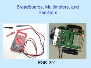
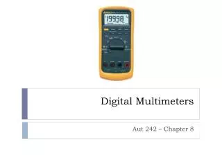
What do meters measure? • A meter is a measuring instrument. • An ammeter measures current. • A voltmeter measures the potential difference (voltage) between two points. • An ohmmeter measures resistance. • A multimeter combines these functions, and possibly some additional ones as well, into a single instrument.
Multimeters measureVoltage VAmperage AResistance Ωand tests for continuity
Selector switch Note the off position.Turn off your meter when not in use.
Multimeter as a Voltmeter To use a multimeter as a voltmeter it is connected in parallel between the two points where the measurement is to be made. The voltmeter provides a parallel pathway so it needs to be of a high resistance to allow as little current flow through it as possible.
Mutimeter as a Voltmeter • Select the DC or AC Volts • Start at the highest volts scale and work your way down. • Probe leads are connected in parallel. • Be very careful to not touch any other electronic components within the equipment and do not touch the metal tips.
Multimeter as a Ammeter • Turn Power Off before connecting multimeter. • Break Circuit. • Move multimeter leads (if needed). • Place multimeter in series with circuit. • Select highest current setting, turn power on, and work your way down. • Turn power off. • Disconnect multimeter. • Reconnect Circuit
Ammeter mode measures current in Amperes. To measure current you need to power off the circuit, you need to break the circuit so that the ammeter can be connected in series. All the current flowing in the circuit must pass through the ammeter. Meters are not supposed to alter the behavior of the circuit, so the ammeter must have a very LOW resistance. The diagrams below show the connection of a multimeter to measure current.
Multimeter as a Ohmmeter • Power always has to be off • Component has to be removed from circuit • Start at lowest Ohm setting or maybe highest.
Component being measured needs to be removed from the circuit.
Review • A meter capable of checking for voltage, current, and resistance is called a multimeter, • As voltage is always relative between two points, a voltage-measuring meter ("voltmeter") must be connected to two points in a circuit in order to obtain a good reading. Be careful not to touch the bare probe tips together while measuring voltage, as this will create a short-circuit! • Remember to always check for both AC and DC voltage when using a multimeter to check for the presence of hazardous voltage on a circuit. Make sure you check for voltage between all pair-combinations of conductors, including between the individual conductors and ground!
Review • When in the voltage-measuring ("voltmeter") mode, multimeters have very high resistance between their leads. • Never try to read resistance or continuity with a multimeter on a circuit that is energized. • Current measuring meters ("ammeters") are always connected in a circuit so the electrons have to flow through the meter. • When in the current-measuring ("ammeter") mode, multimeters have practically no resistance between their leads. This is intended to allow electrons to flow through the meter with the least possible difficulty. If this were not the case, the meter would add extra resistance in the circuit, thereby affecting the current. • Turn selector to off when not in use.