Download
1 / 7
80 likes | 103 Views
The E835 SCI-FI Detector is a scintillating fiber tracking system designed for the E835 experiment at Fermilab. It features coaxial cylindrical layers of scintillating fibers, VLPCs as photosensors, and clear fibers to transmit light signals. The detector has high efficiency, angular resolution, and was assembled in Ferrara with rigorous quality control.

E N D
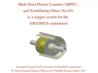
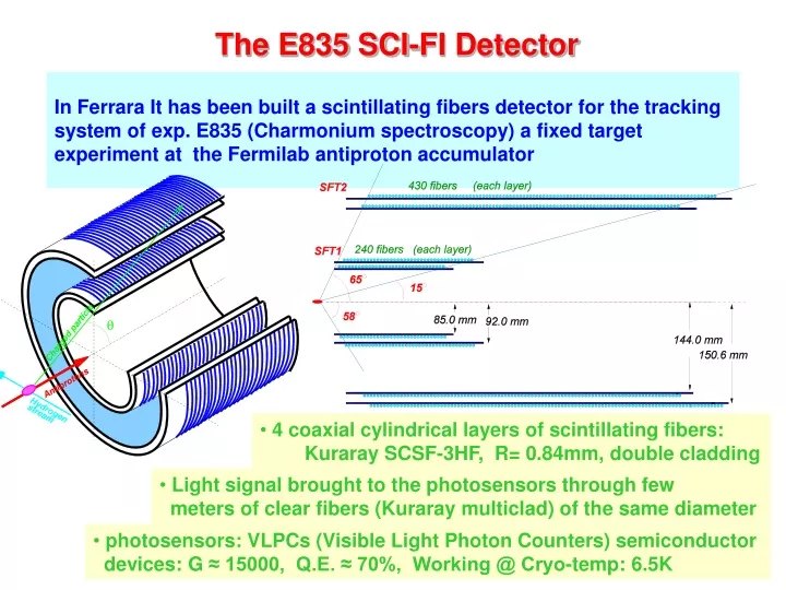
The E835 SCI-FI Detector In Ferrara It has been built a scintillating fibers detector for the tracking system of exp. E835 (Charmonium spectroscopy) a fixed target experiment at the Fermilab antiproton accumulator • 4 coaxial cylindrical layers of scintillating fibers: • Kuraray SCSF-3HF, R= 0.84mm, double cladding • Light signal brought to the photosensors through few • meters of clear fibers (Kuraray multiclad) of the same diameter • photosensors: VLPCs (Visible Light Photon Counters) semiconductor • devices: G ≈ 15000, Q.E. ≈ 70%, Working @ Cryo-temp: 6.5K
E835 SCI-FI Detector layout Scintillating fibers Clear fibers Bending radius: 5cm
E835 SCI-FI Detector performances The detector was designed to measure the polar angle from 0.25 to 0.9 rad Detector Efficiency about 99% Angular Resolution better than 1 mrad
Fiber production Clear Fiber Scintillating fiber ~ 60 cm ~ 250 cm To be wounded around a plexiglas cylinder Splicing point: Scintillating and clear fibers soldered by heating both ends (and protected with a heat shrinking sleeve) Light guide to the photosensors Mirrored end (by sputtering process) • Produced and Tested about 600 fibers • Selected the best 480 to be assembled on the detector (based on the light yield) • About 8 months of work (including R&D)
Tooling Automatic light yield measurement Dark box Polishing machine
Fibers quality control Light yield (a.u.) • The detector was designed and assembled in Ferrara, main operations: • Polishing both ends of each fiber (scintillating and clear) • Splicing of the scintillating fibers with the clear fibers • Sputtering (mirroring) of the not-readout end of the fiber • Quality controls on each fiber: • Light yield • Attenuation length • Light yield as a function of curvature (only on a few fibers) • Reflectivity of the mirrored end • Light loss in the splicing point R (cm) Light yield vs bending radius Reflectivity of the mirrored end Light yield loss in the splicing point
Conclusions • Expertise in Ferrara about building, handling, QC operations of fiber detectors • Facility in Ferrara for Quality Control of fibers: • Dark box about 4 m long instrumented to automatically measure light yield and attenuation lenght of fibers • Machine to polish the fiber ends