Download
1 / 55
550 likes | 771 Views
Institute Of Applied Technology ATE 1012 Grade 10. Electrical Workshop Module 4: Study of Measurement & Test Equipment (2- weeks). Module Objectives. Be familiar with the usage of Multi-meters, Oscilloscopes and Function Generators

E N D
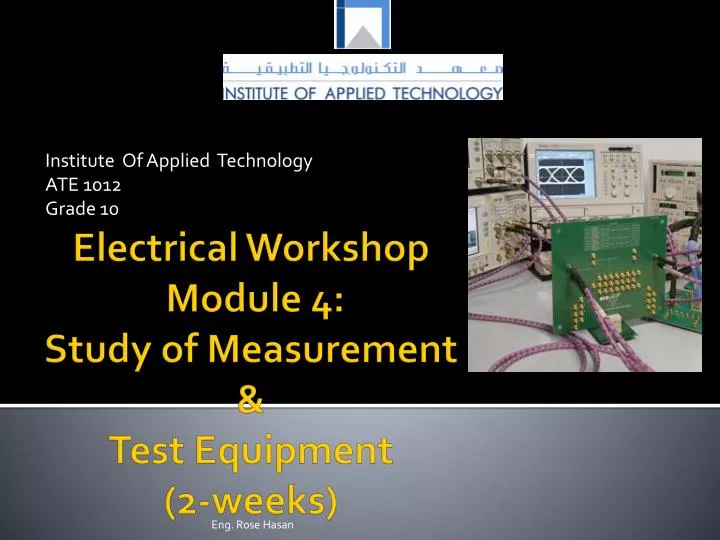
Institute Of Applied Technology ATE 1012 Grade 10 Electrical Workshop Module 4: Study of Measurement &Test Equipment (2-weeks) Eng. Rose Hasan
Module Objectives • Be familiar with the usage of Multi-meters, Oscilloscopes and Function Generators • Perform Measurements of electrical quantities using measuring instruments • Test diodes and connectivity Eng. Rose Hasan
Module Contents • Introduction • Multimeter • Voltage Measurement • Current Measurement • Resistance Measurement • Diode Testing • Continuity Test • Function Generator • Oscilloscope • Practical Tasks Eng. Rose Hasan
Introduaction • Measuring and Test Equipment are used to: • measure electrical quantities • test electrical components • generate different types of signals to test the response of the circuit to that signal. • Measuring and test equipment can be used to: • troubleshoot electrical problems in many industrial and household devices such as batteries, lamps, motor controls and wiring systems Eng. Rose Hasan
Measurement & test equipment functions Eng. Rose Hasan
Multimeters • Purpose: A multi-meter is an electronic measuring instrument that combines several functions in one unit. It is used to: • measure voltage, current and resistance and to test diodes and connectivity Eng. Rose Hasan
Multimeter Functions Eng. Rose Hasan
Multimeter • Types: There are two types of multimeters: • analog & digital Eng. Rose Hasan
Multimeter circuit symbols Eng. Rose Hasan
Digital Multimeter Measurements: Voltage Measurements • Voltage Measurement (Voltmeter): To measure the DC voltage across electrical components in a circuit, follow these steps: • Select on the digital multi-meter's setting switch on the largest voltage range. • Connect the positive (RED) (+) lead to the part of the circuit that is connected to the positive (+) side of the supply (battery). Eng. Rose Hasan
Digital Multimeter Measurements • Connect the negative (BLACK) (-) lead to the part of the circuit that is connected to the negative (-) side of the supply (battery). • Switch on the multi-meter by pressing "POWER" button. Then select the best range that will give you the most accurate results. • Record the reading and the unit that are displayed in the multimeter's display. http://serc.carleton.edu/sp/compadre/interactive/examples/19095.html http://www.physics-chemistry-interactive-flash-animation.com/electricity_electromagnetism_interactive/multimeter.htm Eng. Rose Hasan
Practical Tasks: Activity1: Battery Tester • Items Required: Eng. Rose Hasan
Battery Tester, Steps: • Measure the voltage across the batteries using a multi-meter: Eng. Rose Hasan
Results: • Record your readings on the following table. The true value is the value written on the battery Eng. Rose Hasan
Results: • 3. Compare the measured value with the true value of the voltage written in the battery. Is the measured value close to the real value? If no, state why? • ______________________________________ • 4. You can test a battery using Multi-meter by: • (a) Voltage measurement • (b) Connectivity test • (c) Diode Test Eng. Rose Hasan
Digital Multimeter Measurements: Current Measurements • Current Measurements : To measure the DC current flowing in electrical circuit, follow these steps: • Plug the BLACK (-) probe into the COM input jack and the RED (+) probe into the mA or A input jack. • Adjust the digital multi-meter for current measurements . • Switch off the power in the circuit. Eng. Rose Hasan
Digital Multimeter Measurements: Current Measurements • Break the circuit between elements where the current to be measured. • Insert the probes of the multi-meter in the place where do you break the circuit. • Switch on the multi-meter. • Select the best range that will give you the most accurate results. • Record the reading and the unit that are displayed in the multi-meter's display Eng. Rose Hasan
Steps to measure current Eng. Rose Hasan
Digital Multimeter Measurements: Resistance Measurements • Resistance Measurements (Ohmmeter): To measure the resistance of a resistor, follow these steps: • Turn Off the power to the circuit and remove the components to be tested. • Select on the digital multi-meter's setting switch on the lowest resistance range. Eng. Rose Hasan
Resistance measurement using multimeter • Plug the BLACK (-) probe into the COM input jack and the RED (+) probe into the Ώ input jack. • Connect the probe tips across the component you want to measure its resistance • Switch on the multi-meter and select the best range that will give you the most accurate results. • Record the reading and the unit that are displayed in the multimeter's display. Eng. Rose Hasan
Activity 2: Resistance Measurements • Items Required: Eng. Rose Hasan
Steps: • Measure the resistance across different resistors using a multimeter and color code Eng. Rose Hasan
Results: • 2. Record your readings on the following table Eng. Rose Hasan
Results: • 3. Compare the value of resistance measured by the multi-meter and color code. Are the values close to each other? • ---------------------------------------------------------------------------------------------------------------- Eng. Rose Hasan
Activity 3: Voltage and current Measurements • Items Required: • Resistors (200Ώ), multi-meters • Electricity & Electronics Constructor, EEC470 • Basic Electricity and Electronics Kit EEC471-2 • Power supply unit Eng. Rose Hasan
Steps: • Construct the simple circuit shown below. Use 200 Ώ resistor values. Eng. Rose Hasan
Steps: • Connect the multi-meter to the power supply. • Make sure that the variable dc control knob is fully counter clockwise, and then switch on the power supply. • Increase the applied voltage in 2 V steps from 0 V up to 5 V. Eng. Rose Hasan
Results: • At each step measure the current flowing in the resistor. Record your reading in the following table: Eng. Rose Hasan
Resistance Measurements (Ohmmeter): • To measure the resistance of a resistor, follow these steps: • Turn Off the power to the circuit and remove the components to be tested. • Select on the digital multi-meter's setting switch on the lowest resistance range. • Plug the BLACK (-) probe into the COM input jack and the RED (+) probe into the Ώ input jack. Eng. Rose Hasan
Steps: • Connect the probe tips across the component you want to measure its resistance • Switch on the multi-meter and select the best range that will give you the most accurate results. • Record the reading and the unit that are displayed in the multimeter's display. Eng. Rose Hasan
Diode Testing: • To test if the diode is functioning or not, follow these steps: • Adjust the digital Multi-meter for diode-testing . • Connect the positive lead (Red) (+) to the anode (A(+)) and connect the negative lead (BLACK) (-) to the cathode (K(-)) • Switch on the multi-meter. For a diode in a good condition the reading will be ≤ 300 mV for Ge diode and ≤ 700 mV for Si diode. Eng. Rose Hasan
Results: Eng. Rose Hasan
Steps & Results: • Now connect the (RED) (+)lead to the (K(-)) and (BLACK) (-) lead to the (A(+)) • For a diode in a good condition the reading will be for both types. Eng. Rose Hasan
Continuity Test: • To test if two points are electrically connected, follow these steps: • Turn Off the power to the circuit • Adjust the digital Multi-meter for continuity-testing and Switch on the multi-meter. • When the probes aren't touching, the display shows "1“. Eng. Rose Hasan
Continuity Test: Eng. Rose Hasan
Continuity Test: • When you touch the tips of the probes together, the display changes to a three digit mode. The multi-meter will also emit a beep. Eng. Rose Hasan
Diode Activity • http://www.wisc-online.com/objects/ViewObject.aspx?ID=AMT2104 Eng. Rose Hasan
Function Generator • Purpose: Function generator is used to produce different waveform such as: • Sine • Square • Triangular Eng. Rose Hasan
Function Generator (Purpose) • It is used to test and examine the response of an electrical circuit to that signal. • (i.e. the motor response to a square or triangular signal). Eng. Rose Hasan
Function Generator • Main Control Keys: The function generator has many control keys to control the: • waveform shape • amplitude • Frequency • http://www.physics-chemistry-interactive-flash-animation.com/electricity_interactive.htm Eng. Rose Hasan
The following table shows function generator main keys and their usage. Eng. Rose Hasan
Oscilloscope • Purpose: Oscilloscope is a device that is used to display different waveforms simultaneously • (i.e the input and output of an amplifier). Eng. Rose Hasan
Main Control Keys: Oscilloscope has many control keys to scale the: • amplitude • periods of the displayed waveform. Eng. Rose Hasan
Function Generator • The following table shows some oscilloscope main keys and their usage. Eng. Rose Hasan
Activity 4: Oscilloscope and function generators • Items Required: • Function Generator • Oscilloscope • speaker Eng. Rose Hasan
Measuring Voltage & Time period Eng. Rose Hasan
What is the name of this testing equipment ? Oscilloscope Eng. Rose Hasan
Oscilloscope Screen ( Axis) Eng. Rose Hasan
http://physics-zone.com/lab_oscfunctiongen.html Oscilloscope Lab Worksheet Eng. Rose Hasan