Download
1 / 11
110 likes | 247 Views
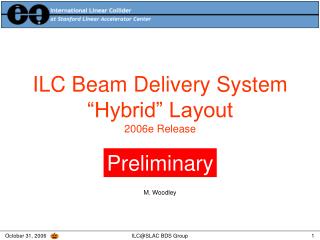
For Overall Layout of ILC Beam Line Layout Choices 200508xx K.Kubo. Possible Beam Line Layout of ILC-(A) Layout based on following choices. Positron source : Prepare both conventional and undulator based. Probably, start with conventional and prepare space for undulator

E N D
For Overall Layout of ILC Beam Line Layout Choices 200508xx K.Kubo
Possible Beam Line Layout of ILC-(A) Layout based on following choices. Positron source: Prepare both conventional and undulator based. Probably, start with conventional and prepare space for undulator Place the undulator at Ebeam = 150 GeV (USTOS) Damping Ring: Dogbone DR, sharing tunnel with Main Linac. Avoid DR - Main Linac interference in the first stage. (Oide - scheme) Turn Around: 180 degree turn around after damping rings. This scheme allows orbit feed-forward after DR.
Schematic Layout and length of each part e- source e- 5GeV Linac (total 400 m) Detector halls Dump halls Turn around e- DR (Straight section 7 km) 6.1 km e- main linac (21.2 km) e- BDS (1.9 km) Spin rotator + Bunch compressor Undulator e+ source, 5 GeV Linac (total ~ 1km) e+ sourece, e+ 5 GeV Linac (total 1 km) Turn around Dump halls e+ DR (Straight section 7 km) e+ main linac (20.2 km) e+ BDS (1.9 km) Spin rotator + Bunch compressor Numbers should be reviewed by experts.
Energy upgrade scheme No DR-ML interference in the first stage. (Oide - scheme) turnaround Electron IP e- DR Undulator for e+ Main Linac for upgrade to 1 TeV Main Linac from the beginning Positron turnaround e+ DR Main Linac for upgrade to 1 TeV Main Linac from the beginning
Possible Beam Line Layout of ILC-(B) Layout without undulator based e+ source Positron source: Conventional. Damping Ring: Dogbone DR, sharing tunnel with Main Linac. Avoid DR - Main Linac interference in the first stage. (Oide - scheme) Turn Around: 180 degree turn around after damping rings. This scheme allows orbit feed-forward after DR.
Possible Beam Line Layout of ILC-(C) Layout without undulator based e+ source Without O-de-scheme Positron source: Conventional. Damping Ring: Dogbone DR, sharing tunnel with Main Linac. Empty tunnel for 500 GeV ECM operation. (It allows major preparations for upgrade during operation.) Turn Around: 180 degree turn around after damping rings. This scheme allows orbit feed-forward after DR.
Of course, there are many other options • Independent DR tunnels • Undulator near IP Decision will be mostly based on: • Choice of e+ source technology • DR design, beam dynamics • Commissioning and Availability consideration (DR-ML sharing tunnel or not) • Overall cost
What should be considered from LET Beam Dynamics (WG1) point of view Low Emittance Preservation in: • Low Emittance Turn Around after DR This is essential for Feed Forward which allow reasonable stability tolerance of extraction kicker of DR. Need to design. • Long, Low Energy, Low Emittance Transport in Layout (A) (before turn around) and Layout (B)(after turn around) • DR-ML field interference (probably WG3b issue)