Download
1 / 31
310 likes | 342 Views
This research focuses on a magnetic measurement system utilizing Hall probe & lock-in amplifier for weak magnetic field detection. It discusses setup, signal recovery, simulation results, data acquisition methods, and future work. The results indicate the importance of precise equipment for noise reduction and the relationship between Hall probe sensitivity and excitation current. The study suggests further analysis for improved certainty in magnetic field measurements.

E N D
WEAK MAGNETIC FIELD MEASUREMENT SYSTEM Andrés G. Delannoy - 14949N SIST Program University of Puerto Rico at Mayagüez Fermi National Accelerator Laboratory August 5, 2008
Agenda • Introduction • Hall Probe • Magnetic Measurement System • Lock-In Amplifier • LabVIEW Simulations • Lo-Pass & Curve Fitting Models • Results • Data Acquisition & Results • DC Probe Excitation • AC Probe Excitation • Probe Frequency Response • Summary & Conclusions • Future Work
Introduction Hall Probe Magnetic Measurement System Lock-In Amplifier
Introduction • HINS 8GeV linear accelerator R&D project • 7.2T @ 250A superconducting focusing magnets • Very low stray field (<0.10 G) requirement proximate to solenoid • Signal must be recovered from electromagnetic noise • Magnetic field measurement necessary at 300K and 4K
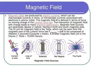
Hall probe • Current through a Hall probe responds to external magnetic field by generating voltage. • The measured voltage is proportional to the magnetic field. V+ Copper winding (2 turns) i B Current Source V- I+ Reference Signal I-
Magnetic measurement system • Setup: • Circular coil with two turns generating 0.201 G/A • Two probes in axis of coil • Cryomagnetics model HSP-T • Sensitivity > 1 mV/G • Nested magnetic shield • Probe excitation methods: • DC • AC • Measurement goals (0.01 G): • Probe Sensitivity (mV/G) • Noise Level (G)
Coil’s Magnetic Field Calculation Biot and Savart Law: At 1A and 12.5cm coil circumference
Lock-In Amplifier Signal Recovery Method
Lock-In Amplifier • Recovers a periodic signal from a noisy environment • Mixes the noisy signal with a reference signal of the same frequency • Applies Low-Pass Filter to rectified signal
LabView Simulations Lo-Pass & Curve Fitting Models Results
LabView Simulation • Laboratory Virtual Instrumentation Engineering Workbench • Graphical programming language (named G) • Used for data acquisition, instrument control, and industrial automation • Based on Virtual Instruments (VI)
Lock-In Simulation:Results • Model approaches: • Chopper + Lo-Pass Model • Full Wave Rectifier + Lo-Pass Model • Fourier Transform Model • Curve-Fitting Model • The modeled filters recovered the simulated signal’s amplitude with 5-10% error (for 1:1 SNR). • A much higher level of certainty is required for our magnetic measurement system.
Data Acquisition DC Probe Excitation AC Probe Excitation
Data Acquisition:Power Supply & Preamp/Filter • SRS Module • SIM 911 BJT Preamp • SIM 965 Analog Filter • HP E3610A • Coil Current Source • Keithley 2400 • DC Probe Current Source
Data Acquisition:Signal Recovery 7265 • DSP Lock-In Amplifier
Data Acquisition: PXI • PCI eXtensions for Instrumentation (PXI) is a modular instrumentation platform used as a basis for building electronic test equipment or automation systems.
DATA ACQUISITION: Data Recording • GPIB Connector & Analog Voltage Output readings were recorded using the NI interface. • Various LabView programs were written to record these data to file.
DATA ACQUISITION: DC Probe Excitation- Sensitivity Probe 1 DC sensitivity ΔV/ΔB = 9.1289 V/G Probe Direct Current Source Low Noise Pre-Amp Coil Direct Current Source Hall Probe Low-Pass Filter Probe 2 DC sensitivity ΔV/ΔB = 6.4051 V/G LabVIEW Voltage Measurement
DATA ACQUISITION:DC Probe Excitation - Noise Level • Probe 1 Noise Level • Probe 2 Noise Level
DATA ACQUISITION:AC Probe Excitation - Sensitivity & Noise Level • Probe 1 Noise Level vs. Frequency • Probe 2 Noise Level vs. Frequency
DATA ACQUISITION:AC Frequency Response - Probe 1 & 2 LabVIEW Voltage Measurement Lock-In Amplifier Lock-In Amplifier Input Probe Direct Current Source 10:1 Transformer Hall Probe
DATA ACQUISITION:Transformer Noise Level vs. Frequency LabVIEW Voltage Measurement Lock-In Amplifier Lock-In Amplifier Input Probe Direct Current Source 10:1 Transformer Lock-In Voltage Without Transformer is Constant with Frequency
Coil Current Source Noise Level Coil Direct Current Source LabVIEW Voltage Measurement 1.1W Shunt Resistor Coil Current Supply contributes 0.00006 G to the noise level
Summary & Conclusions • Software based signal recovery results are inappropriate for the certainty required • Hall Probe sensitivity depends on excitation current (AC vs. DC). • Probe’s 1 & 2 sensitivity dissimilarity may be due to geometric or manufacturing inconsistencies • Lock-In amplifier offers lower noise figures, DC excitation must implement lo-pass filter. • Noise level may be further reduced by using higher precision equipment (power supplies, transformers, etc.)
Future Work • Calculate the change in magnetic field as probe is moved off-center • Detailed noise level analysis at wider range of frequencies for AC probe excitation • Shielding method & effectiveness • Cryogenic temperature measurements
Acknowledgements • Michael A. Tartaglia • Dmitri A. Sergatskov • Magnet Systems Department
References • Griffiths, David J. Introduction to Electrodynamics. 3rd ed. New Jersey: John Wiley & Sons, 1999 p.215-218. • Reitz, John R., and Frederick J. Milford. Foundations of Electromagnetic Theory. London: Addison Wesley, 1960 p.149-159. • Jackson, John D. Classical Electrodynamics. 3rd ed. California: John Wiley & Sons, 1999 p.174-178. • R. Carcagno, et al. Superconducting Solenoid Magnet Test Results. ASC-06, Seattle, 2006. • I. Terechkine, et al. Focusing Solenoid for the Front End of a Linear RF Accelerator. PAQ-07, Albuquerque, 2007. • R. Carcagno, et al. Test Solenoids: Expected Performance and Test Results. TD-06-027, TD-06-028, TD-06-029, FNAL, July 2006.
Questions The Answer to Life, the Universe, and Everything