Download
1 / 75
770 likes | 999 Views
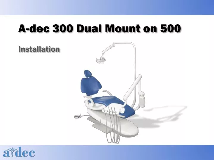
A-dec 300 Dual Mount on 500. Installation. Agenda. General Information Recommended tools Installation Follow through install guide Hands-on install Adjustments Leveling. Learning Objectives. As a result of this training you will be able to:

E N D
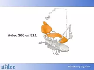
A-dec 300 Dual Mount on 500 Installation
Agenda • General Information • Recommended tools • Installation • Follow through install guide • Hands-on install • Adjustments • Leveling
Learning Objectives • As a result of this training you will be able to: • Identify the different components and options of an A-dec 300 dual mount system on a 511 chair • Complete a full installation • Demonstrate how to use the installation guide • Make adjustments and level
Tools • Recommended Tools: • Sizes are all SAE, no metric • Hex Key Set (inch) • Phillips & standard screw drivers • Socket wrench set (SAE) • Snap ring tool • Adjustable wrench • Needle nose pliers • Combination wrench set (SAE) • Standard pliers • Diagonal cutters • Torpedo Level
511 Chair Box 1 Move the chair from the pallet • Chair and Footswitch
A-dec 511 Chair Installation • Plug in the chair and turn on • Use the three-tap feature to raise the chair • Remove the shipping pin
A-dec 511 Chair Installation • Anchor the chair to the floor
Anchor the Chair To Concrete To Wood Drill a 2” (50 mm) deep hole. Use a 3/8” (0.375 mm) drill. Remove any debris Place the washer on the anchor bolt and insert it into the hole. Tighten the anchor bolt until it is tight against the washer and firmly holds the baseplate to the floor. • Drill a 4” (101 mm) deep hole. Drill through the chair anchoring hole into the concrete. Use a roto-hammer drill. • Remove any debris • Drive the anchor bolt into the hole until the bolt head seats against the chair base. • Tighten the bolt until it is tight against the washer and firmly holds the baseplate to the floor.
Install the Footswitch • Footswitch is optional. If the chair was ordered with a footswitch, install it next.
A-dec 511 Chair Installation • Install the back support and headrest
300 Dual Mount Installation • Lower the back • Install the front mount Screw the leveling bolts (from the kit) into the chair frame, leaving two threads exposed
300 Dual mount Installation • Hang the front mount on the leveling cam
300 Dual Mount Installation • Screw the nuts on the leveling bolts until they are finger tight
Install the Rigid Arms Dental Light or Monitor Mount Dual Rigid Arms Delivery System
Installing the Rigid Arms • Tighten the nut until the arm can move smoothly but is not loose and does not drift
Installing Dual Rigid Arms Place the spacer with its solid side up and its opening toward the hydraulic tubing • Install the spacer
Installing Dual Rigid Arms • Install the toeboard ramps
Leveling the Rigid Arms Leveling Bolts
Leveling • Fully raise the chair back Place level so it is side to side on the mount
Leveling Tighten the stabilizing bolts on each side of the mount until they touch the chair casting Tighten the nuts on the leveling bolts on both sides of the front mount
Delivery Installation A-dec 333 Radius-Style Continental Delivery System on an A-dec 511 chair A-dec 332 Radius-Style Traditional Delivery System on an A-dec 511 chair
Delivery Installation • Install the water bottle
Delivery Installation • Install the flexarm and control head
Delivery Installation • Control head Loosen the button head screw Rotate the control head so it is positioned over the hole for the missing leveling screw Install and tighten 1/4 – 20 x ½” leveling screw Install the 3/8” setscrew
Continental Delivery • Insert whip hooks
Delivery Installation • Route tubing and wiring Umbilical Wrap
Delivery Installation • Route the tubing and wiring Remove the tape from the tubing
Continental Tray Holder • Optional
Traditional Tray Holder • Optional
Dental Light Fully lower the chair base Lubricate the end of the upper rigid arm Route the light cable through the lower rigid arm Insert the upper rigid arm into the lower rigid arm until fully seated Installation is identical for the A-dec 372 or A-dec 572 Dental Light. The A-dec 372 is shown here.
Dental Light Route the cable Install the umbilical wrap
Monitor Mount Route the power and video cables through the mount and down through the rigid arm Install the rotation stop screw and spacer Slide the monitor mount onto the rigid arm
Monitor Mount • Install protective sheath over the monitor cables and secure with cable tie
Monitor Mount • Install the umbilical wrap and route the cables Route the cables Umbilical wrap
Monitor Mount • Optional If the system includes a 100mm VESA standard monitor mounting pattern, use the four screws and nuts to install the adaptor plate
Connections • Connect the electrical wires and data lines Secure the wiring to the bail with cable ties Plug in the red connector Connect the black wire to 0 VAC and the gray wire to 24 VAC Connect the ground wire
Connections • Tubing
Adjustments • Adjust delivery system spring assisted flexarm
Adjustments • Install the delivery system flexarm rotation stop screw
Adjustments • Adjust the control head rotation tension To increase tension, turn the key clockwise. To decrease tension, turn the key counterclockwise.
Adjustments • Adjust the tray rotation tension (Traditional)
Adjustments • Adjust the tray rotation tension (Continental)
Adjustments • Adjust the handpieces • Remove the back cover • Turn the air coolant, water coolant, and drive air controls clockwise to turn them all the way down • Lift a handpiece from the holder • Flip the toggle to water • Step on the foot control • Adjust the water coolant flow until there is 2 drops a second • Step on the foot control • Adjust the air coolant flow until the spray is a fine mist (to increase flow turn the key counterclockwise. To decrease the flow turn the key clockwise)