Download
1 / 53
610 likes | 806 Views
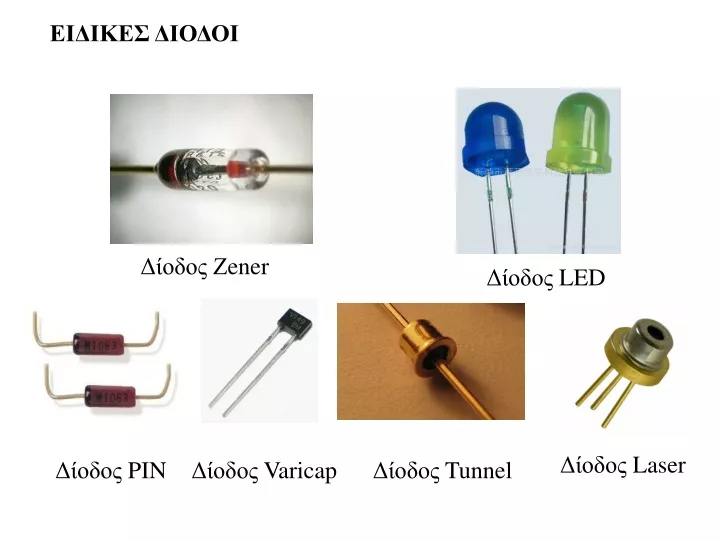
ΕΙΔΙΚΕΣ ΔΙΟΔΟΙ. Δίοδος Ζ ener. Δίοδος LED. Δίοδος Laser. Δίοδος PIN. Δίοδος Varicap. Δίοδος Tunnel. ΕΙΔΙΚΕΣ ΔΙΟΔΟΙ. ΣΤΟΧΟΣ : Να μπορείτε να αναφέρετε τις ειδικές διόδους. Οι ειδικές δίοδοι κατασκευάζονται για διάφορες εφαρμογές. Οι πιο γνωστές ειδικές δίοδοι είναι:. Δίοδος Ζ ener

E N D
ΕΙΔΙΚΕΣ ΔΙΟΔΟΙ Δίοδος Ζener Δίοδος LED Δίοδος Laser Δίοδος PIN Δίοδος Varicap Δίοδος Tunnel
ΕΙΔΙΚΕΣ ΔΙΟΔΟΙ ΣΤΟΧΟΣ: Να μπορείτε να αναφέρετε τις ειδικές διόδους Οι ειδικές δίοδοι κατασκευάζονται για διάφορες εφαρμογές. Οι πιο γνωστές ειδικές δίοδοι είναι: Δίοδος Ζener Δίοδος LED Δίοδος PIN Δίοδος Varicap Δίοδος Tunnel Δίοδος Laser Εμείς θα εξετάσουμε τις διόδους Ζener και τις διόδους LED.
ΣΤΟΧΟΣ: Να μπορείτε να αναφέρετε τα βασικά χαρακτηριστικά και τις χρήσεις των ειδικών διόδων Zener και να σχεδιάζετε το σύμβολο τους. ΔΙΟΔΟΣ ZENER Η Δίοδος Ζένερ (Zener) είναι μια δίοδος που μπορεί να λειτουργεί στην περιοχή κατάρρευσης, δηλαδή στην περιοχή τασης στην οποία οι λοιπές δίοδοι κινδυνεύουν να καταστραφούν. Γι’ αυτό το λόγο ονομάζεται και δίοδος κατάρρευσης. Είναι το βασικότερο εξάρτημα των σταθεροποιητών τάσης που κρατούν την τάση στο φορτίο του κυκλώματος σταθερή ανεξάρτητα από μεταβολές στην τάση της γραμμής και στην αντίσταση του φορτίου. Είναι κάτι σαν ασφάλεια τάσης. Πρακτικά σε ένα κύκλωμα απεικονίζεται ως εξής: Συμβολική αναπαράσταση της διόδου Ζένερ. Το Α = Άνοδος και Κ= Κάθοδος
Μεταβάλλοντας τη στάθμη προσμίξεων των διόδων πυριτίου, στην πράξη μπορούμε να έχουμε τέτοιες διόδους με τάσεις κατάρρευσης από 2 έως 200 βολτ οι οποίες έχουν δυνατότητα λειτουργίας και στις 3 περιοχές ορθής διαρροής και κατάρρευσης. Η δίοδος Ζένερ στην ορθή περιοχή αρχίζει να άγει γύρω στα 0,7 βολτ σαν μια απλή δίοδος. Στην περιοχή διαρροής ανάμεσα στο 0 και την κατάρρευση έχει ένα μόνο ανάστροφο ρεύμα. Ακολουθεί η χαρακτηριστική της διόδου Ζένερ. Χαρακτηριστική ρεύματος-τάσης μιας διόδου Ζένερ με δυναμικό κατάρρευσης 17V. Χρησιμοποιείται διαφορετική κλίμακα για την τάση ορθής πόλωσης (θετική) σε σχέση με αυτή της ανάστροφης πόλωσης (αρνητική).
Στην κατάρρευση έχει μια πολύ απότομη καμπή που συνοδεύεται από μία σχεδόν κατακόρυφη αύξηση του ρεύματος. Ακόμα η τάση στην περιοχή κατάρρευσης είναι σχεδόν σταθερή και περίπου ίση με Uz. Η τιμή αυτή συνήθως καθορίζεται από τα φυλλάδια προδιαγραφών της διόδου σε ένα ρεύμα δοκιμής. Η δίοδος λειτουργεί, όσο το ανάστροφο ρεύμα είναι μικρότερο του Ιzmax. Αν το ρεύμα γίνει μεγαλύτερο από το Izmax, η δίοδος θα καταστραφεί. Η αντίσταση που παρουσιάζει η δίοδος Ζένερ στην περιοχή κατάρρευσης είναι πολύ μικρή, με αποτέλεσμα μια μεγάλη αύξηση του ρεύματος να δημιουργεί μόνο μια μικρή αύξηση της τάσης, που αντιστοιχεί σε λίγα δέκατα του βολτ.
Στο κύκλωμα χρησιμοποιείται πάντοτε μια αντίσταση περιορισμού ρεύματος Rs η οποία συνδέεται πάντα σε σειρά με την δίοδο με σκοπό την προστασία της διόδου. Στο κύκλωμα η τάση στα άκρα της αντίστασης είναι: Vr = Vin – Vz και το ρεύμα μέσα από την αντίσταση και την δίοδο Ζένερ είναι: Ι= (Vin – Vz) / Rs
ΚΑΤΑΣΚΕΥΗ & ΣΥΜΒΟΛΙΣΜΟΣ Η δίοδος ΖΕΝΕΡ κατασκευάζεται από πυρίτιο Si .
ΧΡΗΣΗ Χρησιμοποιείται σε κυκλώματα σταθεροποίησης τάσης για μικρά Ρεύματα. Κατά την ορθή πόλωση συμπεριφέρεται σαν μια κανονική Δίοδος επαφής. Ενδιαφέρων παρουσιάζει όταν πολωθεί ανάστροφα. Ανάλογα με την κατασκευή της σε κάποιο σημείο το ρεύμα αυξάνει απότομα. Όπως θα δούμε στην γραφική της παράσταση , ενώ η τάση στα άκρα της παραμένει σταθερή. Η τάση αυτή ονομάζεται τάση διάσπασης ή ταση ΖΕΝΕR(Vz)
ΛΕΙΤΟΥΡΓΙΑ Η δίοδος για να λειτουργήσει σταθεροποιητικά πρέπει να διαρρέετε από ένα ελάχιστο ρεύμα το Iz min. Επίσης δεν πρέπει να ξεπεράσει τα όρια της ισχύς της για αυτό δεν πρέπει να ξεπεράσει ένα μέγιστο ρεύμα Iz max . Το ρεύμα περιορίζεται από μία αντίσταση R όπως φαίνετε στο πιο κάτω κύκλωμα.
ΑΞΙΟΛΟΓΗΣΗ • Να σχεδιάσετε το ηλεκτρολογικό σύμβολο μιας διόδου ZENER. • Τι θα συμβεί σε μια δίοδο ZENER όταν πολωθεί ανάστροφα; • Που χρησιμοποιούμε τις διόδους ZENER ;
ΣΤΟΧΟΣ:Να μπορείτε να αναφέρετε τα βασικά χαρακτηριστικά και τις χρήσεις των ειδικών διόδων LED και να σχεδιάζετε το σύμβολο της. Δίοδος Εκπομπής Φωτός(Φωτοδίοδος) (LED, Light Emitting Diode) Δίοδος Εκπομπής Φωτός, (LED, Light Emitting Diode), αποκαλείται ένας ημιαγωγός ο οποίος εκπέμπει φωτεινή ακτινοβολίαστενού φάσματος όταν του παρέχεται μία ηλεκτρική τάσηκατά τη φορά ορθής πόλωσης (forward-biased).
Βασικές αρχές Το χρώμα του φωτός που εκπέμπεται εξαρτάται από την χημική σύσταση του ημιαγώγιμου υλικού που χρησιμοποιείται, και μπορεί να είναι υπεριώδες, ορατό ή υπέρυθρο. Το μήκος κύματος του φωτός που εκπέμπεται, και, κατά συνέπεια, το χρώμα του, εξαρτάται από το χάσμα ενέργειας των υλικών, τα οποία χρησιμοποιούνται για την δημιουργία του περάσματος p-n, όπου: p = Υλικό νοθευμένο με αποδέκτες. n = Υλικό νοθευμένο με δότες. Η βασική αρχή των LED είναι μια επαφή p-n η οποία πολώνεται ορθά για να εγχέει ηλεκτρόνια και οπές μέσα στις p και n πλευρές αντίστοιχα. Το εγχεόμενο φορτίο μειονότητας επανασυνδέεται με το φορτίο πλειονότητας στην περιοχή απογύμνωσης ή στην ουδέτερη περιοχή. Σε ημιαγωγούς αμέσου διάκενου η επανασύνδεση οδηγεί σε εκπομπή φωτός αφού η ακτινοβόλα επανασύνδεση κυριαρχεί σε υλικά υψηλής ποιότητας. Σε υλικά έμμεσου χάσματος, η απόδοση εκπομπής φωτός είναι αρκετά φτωχή και οι περισσότερες από τις διαδρομές επανασύνδεσης είναι μη ακτινοβόλες με παραγωγή θερμότητας μάλλον παρά φωτός.
Πλεονεκτήματα των LEDs Απόδοση: Τα LED παράγουν περισσότερο φως ανά watt συγκριτικά με της λάμπες πυράκτωσης. Χρώμα: Τα LED εκπέμπουν φως συγκεκριμένου χρώματος χωρίς την χρήση φίλτρων που απαιτούν οι παραδοσιακοί μέθοδοι φωτισμού. Είναι πιο αποδοτικά και χαμηλώνουν το αρχικό κόστος. Μέγεθος: Τα LED είναι πολύ μικρά (μικρότερα από 2mm) και μπορούν να τοποθετηθούν σε πινάκες αποτύπωσης. Χρόνος ON/OFF: Τα LED έχουν γρήγορη απόκριση. Μια τυπική κόκκινη LED μπορεί να έρθει σε κατάσταση πλήρους φωτεινότητας σε χρόνο microsecond. Τα LED που χρησιμοποιούνται ως συσκευές επικοινωνίας έχουν ακόμα μικρότερους χρόνους απόκρισης. Αντίσταση σε κραδασμούς: Τα LED, όντας στοιχεία στερεάς κατάστασης, είναι δύσκολο να υποστούν ζημιά από κραδασμούς όπως συμβαίνει με τις λάμπες πυράκτωσης και φθορισμού.
Ψυχρό φως: Σε αντίθεση με τις κοινές πήγες φωτός, τα LED εκπέμπουν πολύ λίγη θερμότητα σε μορφή υπέρυθρης ακτινοβολίας που μπορεί να προκαλέσει ζημιά σε ευαίσθητα αντικείμενα ή κατασκευές. Η ενέργεια που χάνεται, διαχέεται ως θερμότητα μέσω της βάσης του LED. Χρόνος ζωής: Τα LED έχουν μεγάλους χρόνους ζωής. Οι ώρες λειτουργίας τους κυμαίνονται από 35.000 έως 50.000 ώρες, αριθμός τεράστιος συγκριτικά με αυτόν των λαμπτήρων πυράκτωσης που κυμαίνεται από 1.000 έως 2.000 ώρες και των λαμπτήρων φθορισμού που κυμαίνεται από 10.000 έως 15.000 ώρες. Εστίαση: Τα LED μπορούν να σχεδιαστούν ώστε να εστιάζουν το φως σε ένα συγκεκριμένο σημείο ή περιοχή. Οι λάμπες πυράκτωσης και φθορισμού απαιτούν ένα εξωτερικό ανακλαστήρα για να συλλέγει το φως και να το κατευθύνει με ένα χρήσιμο τρόπο. Τοξικότητα: Τα LED δεν περιέχουν υδράργυρο όπως οι λάμπες φθορισμού.
Κατασκευή Τα LEDκατασκευάζονται σε διάφορα μεγέθη.
Η κάθοδος του LEDαναγνωρίζετε από το κόψιμο που έχει στη βάση του το LED. και επίσης από το μήκος του ακροδέκτη. (ο μικρός ακροδέκτης, είναι η κάθοδος του LED)
Χρήσεις Με ορατό φως • Σαν λαμπάκια ένδειξης ON-OFF • Για κατασκευή επτά τμηματικών μονάδων ένδειξης, για φωτεινή απεικόνιση αριθμών • Για VU-METER σε Hi-Fi για ένδειξη ψηλού ή χαμηλού σήματος
LED Υπέρυθρων Σε όλα τα τηλεχειριστήρια (Τηλεόρασης, Βίντεο, και άλλων συσκευών) Σε συστήματα ασφάλειας διότι δίνουν αόρατο φως.
Συμβολισμός Άνοδος Α Κ Άνοδος Κάθοδος Κάθοδος
Λειτουργία Για να ελευθερωθεί ένα ηλεκτρόνιο από το άτομο του, απαιτείται ενέργεια. Όταν το ηλεκτρόνιο επιστρέφει πίσω στο άτομο του, τότε ελευθερώνει ενέργεια σε μορφή θερμότητας. Σε μερικά υλικά όμως, η επιστροφή του ηλεκτρονίου στο άτομο του, ελευθερώνει φως, που είναι και αυτό μορφή ενέργειας. Μπροστά από την δίοδο LED υπάρχει ένας φακός για να οδηγεί το φως προς τα έξω και επίσης να το δυναμώνει συγκεντρώνοντας το σε δέσμη (Τομή LED)
ΕΦΑΡΜΟΓΗ Το LED πολώνεται κατά την ορθή φορά και για να αρχίσει να υπάρχει ρεύμα στο κύκλωμα, πρέπει η τάση VD να είναι μεταξύ του 1.2V και του 1.8V, ανάλογα με το LED . Η φωτεινότητα του είναι ανάλογη με το ρεύμα που το διαρρέει.
R Ε = Τάση Πηγής Ι VD= Τάση Πόλωσης 1.2-1.8V VD VR VR = Πτώση Τάσης αντίστασης Ε Ι = Ρεύμα Λειτουργίας του LED Δεδομένα: Ρεύμα για 3mmLED 10-15mA VD= 1.5V ΕΝΔΙΑΜΕΣΗ ΤΙΜΗ Ρεύμα για 5mmLED 15-20mA VR E-VD R = = I I
ΑΞΙΟΛΟΓΗΣΗ 1. Να αναφέρετε μερικές χρήσεις των φωτοδιόδων . 2. Να περιγράψετε τη λειτουργία μιας φωτοδιόδου. 3. Πως αναγνωρίζουμε την άνοδο και την κάθοδο σε μια φωτοδίοδο 4. Να υπολογίσετε την αντίσταση προστασίας για μια φωτοδίοδο 5mm που ενώνεται σε πηγή τάσης 9V. Το ρεύμα λειτουργίας του LED είναι 18mA και η τάση πόλωσης του 1.5V.
ΠΕΙΡΑΜΑΤΙΚΗ ΑΣΚΗΣΗ Να συναρμολογείστε απλό κύκλωμα με LED με προστατευτική αντίσταση και να παρακολουθήσετε την λειτουργία της, μεταβάλλοντας την ένταση του ρεύματος.
Series resistor calculation The formula to calculate the correct resistance to use is where power supply voltage (Vs) is the voltage of the power supply, e.g. a 9 volt battery, LED voltage drop (Vf) is the forward voltage drop across the LED, and LED current (I) is the desired current of the LED. The above formula requires the current in amperes, although this value is usually given by the manufacturer in milliamperes, such as 20 mA. Typically, the forward voltage of an LED is about 1.8–3.3 volts; it varies by the color of the LED. A red LED typically drops 1.8 volts, but voltage drop normally rises as the light frequency increases, so a blue LED may drop around 3.3 volts. resistance, The formula can be explained considering the LED as a and applying Kirchhoff's voltage law (KVL) (R is the unknown quantity):
A "Natural" or "Characteristic" voltage develops across a LED when it is correctly connected in a circuit with a current-limiting resistor to allow a current of between 1mA and 20mA. This voltage is shown in the table above and we normally use the lower value for each colour. However the table shows the voltage varies quite a lot and this depends on the actual crystalline construction of the crystal and the way it is manufactured. You cannot change this and that's why you need to measure the voltage across the LED when building some of the circuits.
CONNECTING A LEDA LED must be connected around the correct way in a circuit and it must have a resistor to limit the current. The LED in the first diagram does not illuminate because a red LED requires 1.7v and the cell only supplies 1.5v. The LED in the second diagram is damaged because it requires 1.7v and the two cells supply 3v. A resistor is needed to limit the current to about 25mA and also the voltage to 1.7v, as shown in the third diagram. The fourth diagram is the circuit for layout #3 showing the symbol for the LED, resistor and battery and how the three are connected. The LED in the fifth diagram does not work because it is around the wrong way.
CHARACTERISTIC VOLTAGE DROPWhen a LED is connected around the correct way in a circuit it develops a voltage across it called the CHARACTERISTIC VOLTAGE DROP. A LED must be supplied with a voltage that is higher than its "CHARACTERISTIC VOLTAGE" via a resistor - called a VOLTAGE DROPPING RESISTOR or CURRENT LIMITING RESISTOR - so the LED will operate correctly and provide at least 10,000 to 50,000 hours of illumination. A LED works like this: A LED and resistor are placed in series and connected to a voltage. As the voltage rises from 0v, nothing happens until the voltage reaches about 1.7v. At this voltage a red LED just starts to glow. As the voltage increases, the voltage across the LED remains at 1.7v but the current through the LED increases and it gets brighter. We now turn our attention to the current though the LED. As the current increases to 5mA, 10mA, 15mA, 20mA the brightness will increase and at 25mA, it will be a maximum. Increasing the supply voltage will simply change the colour of the LED slightly but the crystal inside the LED will start to overheat and this will reduce the life considerably. This is just a simple example as each LED has a different CHARACTERISTIC VOLTAGE DROP and a different maximum current.
In the diagram below we see a LED on a 3v supply, 9v supply and 12v supply. The current-limiting resistors are different and the first circuit takes 6mA, the second takes 15mA and the third takes 31mA. But the voltage across the red LED is the same in all cases. This is because the LED creates the CHARACTERISTIC VOLTAGE DROP and this does not change. It does not matter if the resistor is connected above or below the LED. The circuits are the SAME in operation:
HEAD VOLTAGENow we turn our attention to the resistor.As the supply-voltage increases, the voltage across the LED will be constant at 1.7v (for a red LED) and the excess voltage will be dropped across the resistor. The supply can be any voltage from 2v to 12v or more. In this case, the resistor will drop 0.3v to 10.3v. This is called HEAD VOLTAGE - or HEAD-ROOM or OVERHEAD-VOLTAGE. And the resistor is called the CURRENT-LIMIT resistor.The following diagram shows HEAD VOLTAGE: The voltage dropped across this resistor, combined with the current, constitutes wasted energy and should be kept to a minimum, but a small HEAD VOLTAGE is not advisable (such as 0.5v). The head voltage should be a minimum of 1.5v - and this only applies if the supply is fixed. The head voltage depends on the supply voltage. If the supply is fixed and guaranteed not to increase or fall, the head voltage can be small (1.5v minimum). But most supplies are derived from batteries and the voltage will drop as the cells are used.
Here is an example of a problem:Supply voltage: 12v7 red LEDs in series = 11.9vDropper resistor = 0.1vAs soon as the supply drops to 11.8v, no LEDs will be illuminated. (Sometimes the LEDs will illuminate because some LEDs will have a characteristic voltage that is slightly less than 1.7v and some will illuminate when the voltage is lower than 1.6v - but the brightness will reduce considerably.)
TESTING A LEDIf the cathode lead of a LED cannot be identified, place 3 cells in series with a 220R resistor and illuminate the LED. 4.5v allows all types of LEDs to be tested as white LEDs require up to 3.6v. Do not use a multimeter as some only have one or two cells and this will not illuminate all types of LEDs. In addition, the negative lead of a multimeter is connected to the positive of the cells (inside the meter) for resistance measurements - so you will get an incorrect determination of the cathode lead. CIRCUIT TO TEST ALL TYPES OF LEDs
IDENTIFYING A LED A LED does not have a "Positive" or "Negative" lead. It has a lead identified as the "Cathode" or Kathode" or "k". This is identified by a flat on the side of the LED and/or by the shortest lead. This lead goes to the 0v rail of the circuit or near the 0v rail (if the LED is connected to other components). Many LEDs have a "flat" on one side and this identifies the cathode. Some surface-mount LEDs have a dot or shape to identify the cathode lead and some have a cut-out on one end. Here are some of the identification marks:
LEDs IN SERIES LEDs can be placed in series providing some features are taken into account. The main item to include is a current-limiting resistor.A LED and resistor is called a string. A string can have 1, 2, 3 or more LEDs. Three things must be observed:1. MAXIMUM CURRENT through each string = 25mA. 2. The CHARACTERISTIC VOLTAGE-DROP must be known so the correct number of LEDs are used in any string.3. A DROPPER RESISTOR must be included for each string.The following diagrams show examples of 1-string, 2-strings and 3-strings:
LEDs IN PARALLELLEDs CANNOT be placed in parallel - until you read this: LEDs "generate" or "possess" or "create" a voltage across them called the CHARACTERISTIC VOLTAGE-DROP (when they are correctly placed in a circuit). This voltage is generated by the type of crystal and is different for each colour as well as the "quality" of the LED (such as high-bright, ultra high-bright etc). This characteristic cannot be altered BUT it does change a very small amount from one LED to another in the same batch. And it does increase slightly as the current increases.For instance, it will be different by as much as 0.2v for red LEDs and 0.4v for white LEDs from the same batch and will increase by as much as 0.5v when the current is increased from a minimum to maximum.You can test 100 white LEDs @15mA and measure the CHARACTERISTIC VOLTAGE-DROP to see this range.
If you get 2 LEDs with identical CHARACTERISTIC VOLTAGE-DROP, and place them in parallel, they will each take the same current. This means 30mA through the current-limiting resistor will be divided into 15mA for each LED. However if one LED has a higher CHARACTERISTIC VOLTAGE-DROP, it will take less current and the other LED will take considerably more. Thus you have no way to determine the "current-sharing" in a string of parallel LEDs. If you put 3 or more LEDs in parallel, one LED will start to take more current and will over-heat and you will get very-rapid LED failure. As one LED fails, the others will take more current and the rest of the LEDs will start to self-destruct. The reason why they take more current is this: the current-limit resistor will have been designed so that say 60mA will flow when 3 LEDs are in parallel. When one LED fails, the remaining LEDs will take 30mA each.
Thus LEDs in PARALLEL should be avoided. Diagram A below shows two green LEDs in parallel. This will work provided the Characteristic Voltage Drop across each LED is the same. In diagram B the Characteristic Voltage Drop is slightly different for the second LED and the first green LED will glow brighter. In diagram C the three LEDs have different Characteristic Voltage Drops and the red LED will glow very bright while the other two LEDs will not illuminate. All the current will pass through the red LED and it will be damaged. The reason why the red LED will glow very bright is this: It has the lowest Characteristic Voltage Drop and it will create a 1.7v for the three LEDs. The green and orange LEDs will not illuminate at this voltage and thus all the current from the dropper resistor will flow in the red LED and it will be destroyed.
THE RESISTOR The value of the current limiting resistor can be worked out by Ohms Law. Here are the 3 steps: 1. Add up the voltages of all the LEDs in a string. e.g: 2.1v + 2.3v + 2.3v + 1.7v = 8.4v 2. Subtract the LED voltages from the supply voltage. e.g: 12v - 8.4v = 3.6v 3. Divide the 3.6v (or your voltage) by the current through the string. for 25mA: 3.6/.025 =144 ohms for 20mA: 3.6/.02 = 180 ohms for 15mA: 3.6/.015 = 250 ohms for 10mA: 3.6/.01 = 360 ohms This is the value of the current-limiting resistor.
http://www.talkingelectronics.com/projects/30%20LED%20Projects/30%20LED%20Projects.htmlhttp://www.talkingelectronics.com/projects/30%20LED%20Projects/30%20LED%20Projects.html
Simple LED circuit with 9V battery (5 mm or T1 3/4 sizes are most popular). Series LED circuit (Source Voltage – LED Voltage Drop) / Amps = OHMsAmps = mA/1000 Example:Source Voltage = 9 voltsVoltage Drop = 3.1 volts typical for a blue or white LEDDesired Current = 13 milliamps So the resistor we need is: (9 – 3.1) / ( 13 / 1000 ) = 452 ohms so we will use a 470 Ω resistor.