Download
1 / 77
860 likes | 1.61k Views
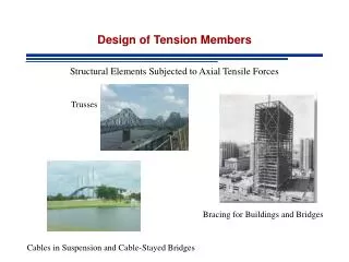
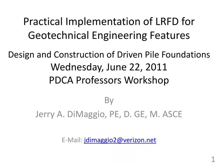
Practical Implementation of LRFD for Geotechnical Engineering Features Design and Construction of Driven Pile Foundations Wednesday, June 22, 2011 PDCA Professors Workshop. By Jerry A. DiMaggio, PE, D. GE, M. ASCE E-Mail: jdimaggio2@verizon.net. ASCE LRFD Webinar Series.

E N D
Practical Implementation of LRFD for Geotechnical Engineering FeaturesDesign and Construction of Driven Pile Foundations Wednesday, June 22, 2011PDCA Professors Workshop By Jerry A. DiMaggio, PE, D. GE, M. ASCE E-Mail: jdimaggio2@verizon.net
ASCE LRFD Webinar Series * Check ASCE website for latest information
Presnetation Assumptions/References • Basic knowledge of: • LRFD (previous webinars) • Basic Deep Foundation Design and Construction • Primary References: • Section 10 of AASHTO (2010, 5th Edition) • List of other references provided at end
Professional Discipline Communication Geotechnical, Structural, Hydraulic, and Construction specialists all play an important role and have different responsibilities on deep foundation projects. Project specific loads, extreme events, performance requirements, scour, pile cap details, specifications, plans construction, pile damage are ALL KEY issues for a successful project! The Geotechnical Design Report is a key communication tool.
10.7.1 GENERAL • Consider spread footings first. • Basic guidelines for driven pile configurations • Minimum spacing 2.5 pile diameters or 30 inches. • Minimum of 9 inches pile cap edge and be embedded 12 inches into the pile cap or if with strands or bars then the pile embedment should be 6 inches. • Piles through embankments should extend 10 ft into original ground or refusal on rock. Maximum of 6 inch fill size. • Batter Piles: stiffness, don’t use in downdrag situations, concern in seismic situations.
DW EH EV ES DC LL DD EQ CT WA
Load Factors for Permanent Loads, gp AASHTO Table 3.4.1-2
Downdrag • “Geotechnical” load • Can be significant particularly given the max load factors • Articles 3.4.1 and 3.11.8 15
DISCUSSED IN PREVIOUS WEBINAR ON SUBSURFACE INVESTIGATIONS – Next Offering on August 18, 2011 AASHTO Section 10.4 Soil and Rock Properties
Deep Foundation Selection • Method of support • Bearing material depth • Load type, direction and magnitude • Constructability • Cost • Expressed in $/kip capacity • Include all possible costs
Strength Limit State Driven Piles ARTICLE 10.5.3.3 Axial compression resistance for single piles Pile group compression resistance Uplift resistance of single piles Uplift resistance of pile groups Pile punching failure in weaker stratum Single pile and pile group lateral resistance Constructability, including pile drivability
SPECIAL DESIGN CONSIDERATIONS Negative shaft resistance (downdrag) Lateral squeeze Scour Pile and soil heave Seismic considerations
10.5 LIMIT STATES AND RESISTANCE • Strength Limit State (will be discussed later) • Structural Resistance • Geotechnical Resistance • Driven Resistance • Service Limit State • Resistance Factor = 1.0 (except for global stability) • Extreme Event Limit State • Seismic, superflood, vessel, vehicle • Use nominal resistance
Settlement of Pile GroupsArticle 10.7.2.3.1 [Hannigan (2006)] Treat as equivalent footings Categorize as one of the 4 cases shown here
10.7.2.4 Horizontal Loads and Pile Moments Dx Dx Fx H2 H1 M2 M1
Horizontal Response Isolated Group Assumes nominal resistance is adequate No consideration of possible brittle response of geomaterial LPILE type p-y model or Strain Wedge Method
P-y Results for Pile Groups AASHTO Figure 10.7.2.4-1
Moment Moment Pile Head Fixity Dx Dx 30
Tolerable Movements and Movement Criteria 10.5.2.2 Service loads for settlements, horizontal movements and rotations. Omit transient loads for cohesive soils Reference movements to the top of the substructure unit. Angular Distortion (C10.5.2.2)
Methods for Determining Structural Resistance Axial compression Combined axial and flexure Shear Concrete – Section 5 LRFD Specifications Steel – Section 6 Wood – Section 8
Factors AffectingAllowable Structural Pile Stresses Average section strength (Fy, fc’, wood crushing strength) Defects (knots in timber) Section treatment (preservation for timber) Variation in materials Load factor (overloads or pile damage)
Structural Resistance Factors10.7.3.13 Pile Structural Resistance Concrete (5.5.4.2) Axial Comp. = 0.75 Flexure = 0.9 (strain dependent) Shear = 0.9 Steel (6.5.4.2) Axial = 0.5-0.7 Combined Axial= 0.7-0.8 Flexure = 1.0 Shear = 1.0 LRFD Specifications Timber (8.5.2.2 and .3) Compression = 0.9 Tension = 0.8 Flexure = 0.85 Shear = 0.75
Determining Nominal Axial Geotechnical Resistance of Piles • Field methods • Static load test • Dynamic load test (PDA) • Driving Formulae • Wave Equation Analysis • Static analysis methods
Geotechnical Nominal Resistance of Piles: Static Load Tests ASTM D1143 (10.7.8.2)
Wave Equation Results 195 MPa 1480 kN 2.6 m 68 blows / 0.25 m
Static Analysis Methods(Article 10.7.3.8.6) Static analysis methods and computer solutions are used to: ● Calculate pile length for loads ● Determine number of piles ● Determine most cost effective pile type ● Calculate foundation settlement ● Calculate performance under uplift and lateral loads
Static Analysis Methods Primary use is for pile length estimation for contract drawings and feasibility. Secondary use for estimation of downdrag, uplift resistance and scour effects Should rarely be used as sole means of determining pile resistance. ONLY IN SPECIAL SITUATIONS!
Large Pile Diameter Resistance Total Resistance A Side Resistance B D Resistance C Tip Resistance RS Vertical Displacement RP RR = fRn = fqpRp + fqsRs
RR = fRn fRn = fqpRp + fqsRs RP = AP qP RS = AS qs Computation of Static Geotechnical Resistance RS RP AASHTO 10.7.3.7.5-2