Download
1 / 52
4.25k likes | 11.18k Views
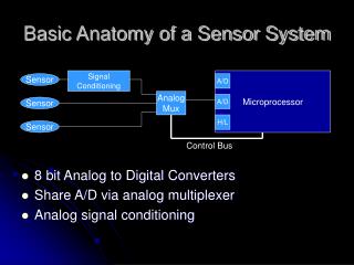
Chapter 4 : Signal conditioning. 4.1 Introduction to signal conditioning 4.2 Bridge circuits 4.3 Amplifiers 4.4 Protection 4.5 Filters. Introduction. ELECTRICAL MEASUREMENT SYSTEM. WHY?. Easy to transmit signal from measurement site the data collection site

E N D
Chapter 4 : Signal conditioning 4.1 Introduction to signal conditioning 4.2 Bridge circuits 4.3 Amplifiers 4.4 Protection 4.5 Filters BMCC 3743Signal Conditioning
Introduction BMCC 4743 Signal Conditioning
ELECTRICAL MEASUREMENT SYSTEM WHY? • Easy to transmit signal from measurement site • the data collection site • Easy to amplify, filter and modify • Easy to record the signal BMCC 4743 Signal Conditioning
Signal conditioning • Used in factory or machine automation : to convert sensor or transducer measurement signal levels to industry standard control signals • Provide computer and control system manufacturers a common communication method to effectively receive and transmit measurement and control data • Examples of measurement data : temperature or AC/DC voltage/current signals from various transducers • Examples of control data : on/off signals for a heating element or proportional signals for a valve actuator. BMCC 4743 Signal Conditioning
Signal conditioning BMCC 4743 Signal Conditioning
Bridge circuits BMCC 4743 Signal Conditioning
Bridge circuits • Used to convert impedance variations into voltage variations • Can be design so the voltage produced varies around zero • Amplification can be used to increase voltage level for increased sensitivity to variation of impedance BMCC 4743 Signal Conditioning
Wheatstone bridge • D : voltage detector BMCC 4743 Signal Conditioning
Exercise 1 Determine; • R4 if a Wheatstone bridge nulls with R1 = 1000 Ω, R2 = 842 Ω, and R3 = 500 Ω. • The voltage offset if the supply voltage is 10.0 V. The resistors in a bridge are given by R1 = R2 = R3 = 120 Ω and R4 = 121 Ω. BMCC 4743 Signal Conditioning
Galvanometer detector BMCC 4743 Signal Conditioning
Exercise 2 A bridge circuit has a resistance of R1 = R2 = R3 = 2.00 kΩ and R4 = 2.05 kΩ and a 5.00 V supply. If a galvanometer with a 50.0 Ω internal resistance is used for a detector, calculate the offset current. BMCC 4743 Signal Conditioning
Bridge resolution • Resolution function of detector : to determine the bridge offset • Resistance resolution : resistance change in 1 arm bridge that causes an offset voltage equal to detector resolution • Detector can measure change of 100 µV BMCC 4743 Signal Conditioning
Resolution • The smallest discernible change in input; the smallest change in input that manifests itself as perceptible change in output that can be measured (example : 0.000 1 mm) • Primary factor in deciding precision • Good resolution does not imply in good precision BMCC 4743 Signal Conditioning
Current balance bridge BMCC 4743 Signal Conditioning
Current balance bridge • Used current to null bridge BMCC 4743 Signal Conditioning
Exercise 3 A current balance bridge has a 10 V supply voltage and resistors R1 = R2 = 10 kΩ, R3 = 1 kΩ, R4 = 950 Ω, R5 = 50 Ω and a high impedance null detector. Determine the current required to null the bridge if R3 increased by 1 Ω. BMCC 4743 Signal Conditioning
Potential measurements using bridges BMCC 4743 Signal Conditioning
Potential measurements using bridges BMCC 4743 Signal Conditioning
Exercise 4 A bridge for potential measurement nulls when R1 = R2 = 1 kΩ, R3 = 605 Ω, and R4 = 500 Ω with a 10.0 v supply. Determine the unknown potential. BMCC 4743 Signal Conditioning
Exercise 5 A current balance bridge is used for potential measurement. The fixed resistors are R1 = R2 = 5 kΩ, R3 = 1 kΩ, R4 = 990 Ω, and R5 = 10 Ω with a 10 V supply. Calculate the current necessary to null the bridge if the potential is 12 mV. BMCC 4743 Signal Conditioning
Amplifiers BMCC 4743 Signal Conditioning
Op amp characteristic BMCC 4743 Signal Conditioning
Summing amplifier BMCC 4743 Signal Conditioning
Noninverting amplifier BMCC 4743 Signal Conditioning
Exercise 7 Design a high impedance amplifier with a voltage gain of 42 if R1 = 1 kΩ is chosen. BMCC 4743 Signal Conditioning
Differential amplifier • The transfer function; • Common mode rejection; BMCC 4743 Signal Conditioning
Voltage-to-Current converter BMCC 4743 Signal Conditioning
Current-to-Voltage converter BMCC 4743 Signal Conditioning
Exercise 8 For a voltage-to-current converter using an op-amp, show that the relationship between current and voltage is given by . BMCC 4743 Signal Conditioning
Integrator BMCC 4743 Signal Conditioning
Exercise 9 Use an integrator to produce a linear ramp voltage rising at 10 V per ms. Determine the R and C. BMCC 4743 Signal Conditioning
Differentiator BMCC 4743 Signal Conditioning
Linearization BMCC 4743 Signal Conditioning
Linearization BMCC 4743 Signal Conditioning
Filters BMCC 4743 Signal Conditioning
Filters • Filter : a circuit that is designed to pass signals with desired frequencies and reject or attenuate others • 4 types of filters: • Low-pass filter: passes low frequencies and stops high frequencies • High-pass filter: passes high frequencies and rejects low frequencies • Band-pass filter: passes frequencies within a frequency band and blocks or attenuates frequencies outside the band • Band-reject filter: passes frequencies outside a frequency band and blocks or attenuates frequencies within the band BMCC 4743 Signal Conditioning
Low-pass RC filter BMCC 4743 Signal Conditioning
Low-pass RC filter • Critical frequency: • Output-to-input voltage ratio: BMCC 4743 Signal Conditioning
Exercise 10 A measurement signal has a frequency less than 1 kHz, but there is unwanted noise at about 1 MHz. Design a lowpass filter that attenuates the noise to 1% if a capacitor 0.01 µF has been used. What is the effect on the measurement signal at its maximum of 1 kHz? BMCC 4743 Signal Conditioning
High-pass RC filter BMCC 4743 Signal Conditioning
High-pass RC filter • Critical frequency: • Output-to-input voltage ratio: BMCC 4743 Signal Conditioning
Exercise 11 Pulses for a stepping motor are being transmitted at 2000 Hz. Design a highpass filter to reduce 60 Hz noise and reduce the pulses by no more than 3 dB. BMCC 4743 Signal Conditioning
Design Methods • Determine critical frequency, fc • Select standard capacitor (µF – pF) • Calculate required resistance (1 kΩ - 1 MΩ) • Use nearest resistance standard value to calculated value • Consider tolerance in resistors and capacitors BMCC 4743 Signal Conditioning
Practical considerations • Very small resistance -> lead to large currents and loading effects -> avoid large capacitance (R= kΩ -MΩ, C= µF – pF) • The exact fc is not important, choose R and C of approximately to the fc • Isolation filter input/output with voltage follower • Cascade RC filters to improved fc sharpness -> consider loading BMCC 4743 Signal Conditioning
Band-pass RC filter BMCC 4743 Signal Conditioning
Band-pass RC filter • Critical frequency: • Output-to-input voltage ratio: BMCC 4743 Signal Conditioning
Exercise 12 A signal conditioning system uses a frequency variation from 6 kHz to 60 kHz to carry measurement information. There is considerable noise at 120 Hz and at 1 MHz. Design a bandpass filter to reduce the noise by 90%. What is the effect on the desired passband frequencies if r = 0.01? Determine all the resistors and capacitors. BMCC 4743 Signal Conditioning
Band-pass RC filter BMCC 4743 Signal Conditioning
Band-reject RC filter BMCC 4743 Signal Conditioning
Twin-T notch filter BMCC 4743 Signal Conditioning