Download
1 / 1
10 likes | 128 Views
thermal insulation, windows. cooling of electronics with CO 2 cooling system and of Si sensors with dry gas operation temperature: ~ -5 o C to -10 o C. target chamber, MVD, beam pipe. maintenance. power dissipation: targeted prototypes: 37 kW optimized distribution: 27 kW

E N D
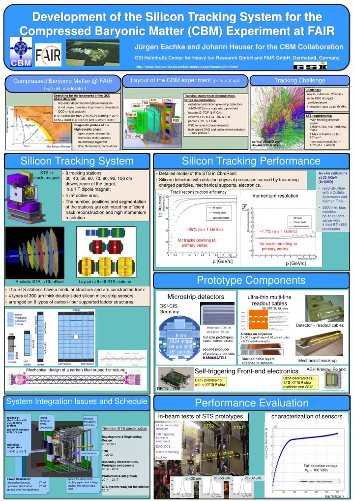
thermal insulation, windows cooling of electronics with CO2cooling system and of Si sensors with dry gas operation temperature: ~ -5oC to -10 oC target chamber, MVD, beam pipe maintenance power dissipation: targeted prototypes: 37 kW optimized distribution: 27 kW spread over four quadrants space for electronics, cooling pipes, low voltage cables and optical data links σ =58 m σ =32 m σ =32 m Development of the Silicon Tracking System for the Compressed Baryonic Matter (CBM) Experiment at FAIR Development of the Silicon Tracking System for the Compressed Baryonic Matter (CBM) Experiment at FAIR STS2 STS1 Realistic STS in CbmRoot Track reconstruction efficiency STS in dipole magnet Layout of the 8 STS stations Mechanical design of a carbon fiber support structure. STS0 Jürgen Eschke and Johann Heuser for the CBM Collaboration GSI Helmholtz Center for Heavy Ion Research GmbH and FAIR GmbH, Darmstadt, Germany http://www.fair-center.eu/en/fair-users/experiments/cbm.html 2.4 GeV protons Tracking Challenge Layout of the CBM experiment (e+e- set up) Compressed Baryonic Matter @ FAIR – high μB, moderate T: Challenge: • Au+Au collisions , 25A GeV • up to 1000 charged • particles/event • interaction rates up to 10 MHz • Searching for the landmarks of the QCD phase diagram: • first order deconfinement phase transition • chiral phase transition (high baryon densities!) • QCD critical endpoint • in A+A collisions from 2-45 AGeV starting in 2017 • CBM + HADES at SIS100 and CBM at SIS300 • Tracking, momentum determination, • vertex reconstruction: • radiation hard silicon pixel/strip detectors • (MVD+STS) in a magnetic dipole field • hadron ID: TOF (& RICH) • electron ID: RICH & TRD & TOF • photons, π0, η: ECAL • PSD for event characterization • high speed DAQ and online event selection → rare probes ! Diagnostic probes of the • high-density phase: • open charm, charmonia • low-mass vector mesons • multistrange hyperons • flow, fluctuations, correlations STS requirements: • main tracking detector system: efficient, fast, rad. hard, low-mass • 1 MeV n fluenceup to ~ 1014/cm2 • momentum resolution ~ 1.7%(p > 1 GeV/c) Silicon Tracking System Silicon Tracking Performance central URQMD event: Au+Au @ 25AGeV • 8 tracking stations: 30, 40, 50, 60, 70, 80, 90, 100 cm downstream of the target, in a 1 T dipole magnet; • 4 m2active area; • The number, positions and segmentation of the stations are optimized for efficient track reconstruction and high momentum resolution. • Detailed model of the STS in CbmRoot: • Silicon detectors with detailed physical processes caused by traversing charged particles, mechanicalsupports, electronics. • Au+Au collisionsat 25 AGeV(UrQMD) • reconstruction with a Cellular Automaton and KalmanFilter • 2500 min. bias events/s on an 80-core server with 4 Intel E7-4860 processors TOF ECAL TRD RICH momentum resolution Magnet [%] [efficiency] PSD STS + MVD ~95% (p > 1 GeV/c) ~1.7% (p > 1 GeV/c) for tracks pointing to primary vertex for tracks pointing to primary vertex p [GeV/c] p [GeV/c] Prototype Components • The STS stations have a modular structure and are constructed from: • 4 types of 300 µm thick double-sided silicon micro-strip sensors, • arranged on 8 types of carbon-fiber supported ladder structures. Microstrip detectors ultra-thin multi-line readout cables GSI-CIS, Germany SE SRTIIE, Ukraine Detector + readout cables thickness: 300 m strip pitch: 58m Al strips on polyamide 2 x 512 signal lines of 60 μm eff. pitch full-size prototypes: CBM01, CBM03, CBM05 < 0.2% radiation lengths secondproducer of prototype sensors HAMAMATSU 6 cm 1024 strips 58 μm pitch 15° stereo Stacked cable layers attached to sensors Mechanical mock-up Self-triggering Front-end electronics AGH Krakow, Poland CBM-dedicated FEE STS-XYTER chip availableend2012 Early prototyping with n-XYTER chip ~60 cm length DETNI - GSI System Integration IssuesandSchedule Performance Evaluation In-beam tests of STS prototypes characterization of sensors silicon micro strip detectors self-triggering front-end electronics DAQ, DCS online monitoring tracking Timeline STS construction Development & Engineering Design 2012-2013 TDR 10/2013 Assembly infrastructures, Prototype components 2012 – 2014 Production & integration 2014 – 2017 STS system ready for Installation 2017 dipole magnet Full depletion voltage Vfd ~ 100 Volts