Download
1 / 57
590 likes | 753 Views
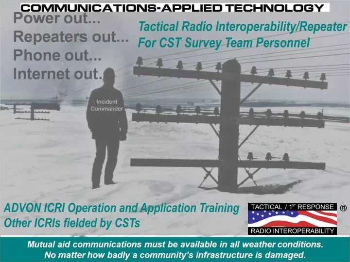
ADVON ICRI Operation and Application Training Other ICRIs fielded by CSTs. Tactical Radio Interoperability/Repeater For CST Survey Team Personnel. ®. Administrative Information. Sign-in Sheets for completion certificate Course Evaluation forms to be completed before you leave.

E N D
ADVON ICRI Operation and Application Training Other ICRIs fielded by CSTs Tactical Radio Interoperability/Repeater For CST Survey Team Personnel ®
Administrative Information • Sign-in Sheets for completion certificate • Course Evaluation forms to be completed before you leave • Website Contains • Slides • Note Pages Please note: the training presentation has greater detail in the notes section of each slide. Use this for to review independently or a guide for a training session.
Objectives • Identify general information and description of the ADVON ICRI • Describe the principles of operation of the ADVON ICRI as delivered • Review what other ADVON ICRI capabilities have been implemented by CSTs • Review what other ADVON ICRI capabilities would enhance the CST commo activities • Review PM procedures for the ADVON ICRI
A solution to multitude of tactical communications problems… • Mutual Aid Radio Interoperability • In-building/below grade repeater • Range Extension BLOS
ICRI Configurations Used by the CSTs Radio Interoperability KitGeneral Information and Description
ADVON ICRI • 4.5 lbs • 11” x 3” x 7” • Two talk groups • Five radio interconnect ports • Low band, VHF, 220-900MHz legacy and P25 portable/mobile compatible • Bridge radios with incompatible encryption • Telephone modular (RJ22) port • Cell and land-line telephone compatible • Commercial and military sat phone compatible • Adjustable audio “buffer” • Can be linked to 2nd ICRI • Can be linked the UCS ACU-1000 • Wide range of power sources: “AA” batteries, external DC/AC
ICRI-2PED with CABLE-REEL • 5.9 lbs (ICRI) • 8.0” x 9.5” x 1.5” (ICRI) • Two Radio I/O ports + telephone port • Internal 6 “AA” battery housing provides a 24+ hour duty cycle; also uses external DC or AC • Primary Use: Repeater * * ICRI-2PE shown
ICRI-E • Bridging: five L-M-R, cell or land-line telephone, MSAT, Iridium • 7.0 lbs • 10.5” x 9.5” x 6.0” • GROSS DECON-ABLE, WATER-PROOF, SAND-PROOF • Internal housing for eight (8) “AA” alkaline/primary batteries provide an 24+ hour duty cycle; also uses external DC or AC • Uses standard “military” connectors and compatible with the H-250/350 “green gear” handset
ICRI-G2 Satellite Radio Interface Connect any radio (mobile or portable) to G2 for rapidly deployable link to MSAT PTT satellite. No additional power or modification to equipment Place in between MSAT handset and transceiver Includes delay for initial satellite acquisition
Description-Pt. 1 • A small, lightweight interconnect assembly for “bridging” dissimilar radios • The ICRI performs two primary functions: • Receive incoming audio • Distribute audio • Quick Setup • VOX Keying
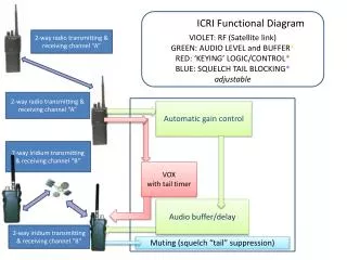
ICRI Functional Diagram BLUE: RF* GREEN: AUDIO LEVEL and BUFFER* LT BLUE: ‘KEYING’ LOGIC/CONTROL* VIOLET: SQUELCH TAIL BLOCKING* * adjustable 2-way radio transmitting frequency “A” or trunking assigned channel 2-way radio receiving frequency “A” or trunking assigned channel Automatic gain control 2-way radio receiving frequency “B” or trunking assigned channel VOX with tail timer Audio buffer/delay 2-way radio transmitting frequency “B” or trunking assigned channel Muting
Interoperability Do’s and Don’ts • Maintain COMSEC • Verify only one bridge connected on frequencies • Maintain RF Separation • Power sources • Other radios • In-line audio amplifiers • Don’t use “SCAN” mode on connected radios.
Preoperational Activities • Power • Radio interconnect cables • Agency radios • Radio frequency (in-band/cross-band)
Components • Controls • Indicators • Power Sources • Pelican Cases • Options
ICRI Controls Talk group switch Power (DC input) jack Volume adjustment handset/headset Radio jack (1 through 5) Telephone/acoustic coupler jack Handset/headset jack
ICRI Indicators OK/Low input voltage LEDs Active VOX LED indicator
Power • AA Battery Power • AC Power • DC Power
“AA” Battery Pack • Accepts 8 “AA” batteries • 24+ hours of continuous operation • LEDs indicate input voltage. • Use fresh alkaline batteries The battery housing is comprised of two parts; the cover and an internal tray. NO TOOLS ARE NEEDED TO REMOVE THE cover AND REPLACE THE BATTERIES.
AC Power • Accepts 7-24V • Two pin screw-type connector Note: Align the plug’s “key” with the jack’s “keyway” before attempting to insert the plug.
DC Power • Accepts 7-24V • Two pin screw-type connector • Cigarette lighter • Alligator clips
ICRI handset • Compatible with the C-AT handset • Connection and controls on the front of the ICRI • Maybe replaced with a headset for hands-free operation • Use as an: • Incident Commander interface • Troubleshooting tool • Setup tool
Land Mobile Radio Interface – Pt. 1 • Verify Radio • Operation • Batteries • TX/RX • Radio Settings • Channel • Volume • Connect Interface cable • Radio speaker is disabled NOTE: Radio interconnect cables are generally specific to a commercial radio brand and model, although some manufacturers use the same connector for several radio models. Interconnect cables provided by C-AT have a seven digit part number label on the cable.
Land Mobile Radio Interface – Pt. 2 • Attach interface cable • Select Talk Group • Verify LED lights • Mobile radios NOTE: Connect each radio separately to the ICRI, use the provided handset to verify the radio is functioning before connecting the next radio.
Side Jacks Telephone jack Link port
Telephone Interface • cellular* • land-line* • commercial satellite phones** • *Secure or Non-secure • ** Iridium, MSV, Enmarsat, GlobalStar
Telephone Interface – Cellular* • Insert the 2.5mm plug into the cell phone headset jack. • Connect to ICRI • Adjust volume to ICRI • Set phone for auto answer • Place call *secure or non-secure
Telephone Interface – Land-line* Use the telephone’s handset cable by unplugging the coil cord from the bottom of the handset and connecting to ICRI. * Secure (STE) or non-secure (analog or digital)
Link ICRIs • Use standard CAT5 cable to link multiple ICRI’s up to 200’ apart • All radios on each Talk Group linked • No reboot needed
Cable reel • Positioning one or more of the radios, to be connected to the ICRI at a distance greater than the length of the interface cable may be desirable for one of several operational reasons: • The personnel associated with a radio will be located inside a building for which there is poor RF coverage from the ICRI’s location. • The personnel associated with a radio will be located inside a tunnel or other below grade area for which there is poor RF coverage from the ICRI’s location. • Radios operating in very close proximity to one another, negatively affect the performance of other another, such as receiver desensing.
In-Building/Below Grade Repeater250’ & 500’ Cable Extension Reel Interior building/below grade radio interface cable reel and mount for hand-held radio. Up to 5000’ of cable runs have been successfully used in the subway and mall incidents. Washington, DC METRO subway entry with 800MHz Motorola XTS5000 radio
Reel setup • Set-up of the cable-reel • Equipment required: ICRI, cable-reel, radio interface cable for radio to be placed in the area of poor RF coverage. • Place the radio on the reel’s right angle support and secure it in-place with the Velcro™ strap. • Connect the cable end that exits from the side of the reel to the radio interface cable. Be sure to align the keyway and secure the connectors together with the locking ring on the male connector. • Connect the unspooled cable to a radio port on the ICRI. Be sure to align the keyway and secure the connectors together with the locking ring on the male connector. • If needed, connect additional cable reels between the ICRI and the first reel.
Reel link • Multiple reels of cable can be linked together. There will be no degradation of the communications link for up to 5000’ of cable. BUT, it is important to note that if the cable is run near a source of high electrical energy, “noise” from such a device can be expected to be induced into the cable and reduce---possibly significantly---the quality of the communications. • It is strongly recommended that the radio link be tested before the personnel enter the area of poor RF propagation, so that any defects with the cable or the connections will be noted before a safety issue arises--due to a lack of radio communications.
Optional adapters for cable-reel for vertical entries Reversal cables invert connection ends of the cable reel When to use: Using the cable-reel to place a radio in a stairwell, on a building roof, hill or tree top to enhance the operating range of the radio, then it may be preferable to have the reel located beside the ICRI and the radio connected to the “free” end of the cable to be unspooled.
Bridge Unit ID® • In response to the critical disruption of radio communications that can occur when more than one "bridge" device links radios with identical frequencies, causing heterodyning, C-AT has developed the Bridge Unit ID for the ICRIs. • The “announcement” radically simplify the task of locating the owner of the interfering bridge and in shutting the device down. • The Bridge Unit ID is a digitized speech message selected by the user organization / agency. The “ID” is transmitted when the ICRI is first powered up on all talk groups, and then at preset intervals of 0, 5, 10, or 15 minutes. • The announcement automatically “skips” a broadcast if there is any radio activity at the interval mark.
Remote DTMF Control • Functions • Setup • There must be a radio connected to the Land Mobile Radio Interface #1 jack. • DTMF sequence for unit: __ __ __ __ _ _ • 10 All Off (Interoperability “bridge” disabled) • 11 All inputs on Talk Group 1 • 12 All inputs on Talk Group 2 • 13 Re-enable “bridge”/Talk Groups
ICRI Board Adjustments – Pt. 2 DO NOT USE
Desensing – Pt. 1 Strong Signal
Interoperability Do’s and Don’ts • Maintain COMSEC • Verify only one bridge connected on frequencies • Maintain RF Separation • Power sources • Other radios • In-line audio amplifiers • Don’t use “SCAN” mode on connected radios.