Download
1 / 15
190 likes | 507 Views
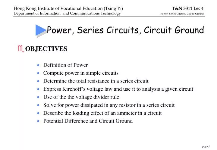
Power, Series Circuits, Circuit Ground. OBJECTIVES Definition of Power Compute power in simple circuits Determine the total resistance in a series circuit Express Kirchoff’s voltage law and use it to analysis a given circuit Use of the the voltage divider rule

E N D
Power, Series Circuits, Circuit Ground • OBJECTIVES • Definition of Power • Compute power in simple circuits • Determine the total resistance in a series circuit • Express Kirchoff’s voltage law and use it to analysis a given circuit • Use of the the voltage divider rule • Solve for power dissipated in any resistor in a series circuit • Describe the loading effect of an ammeter in a circuit • Potential Difference and Circuit Ground
Notation of D.C. quantities • Direction of V and I • Source Load
Example • Compute the power supplied to the electric heater shown below, using all three power formula.
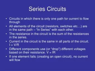
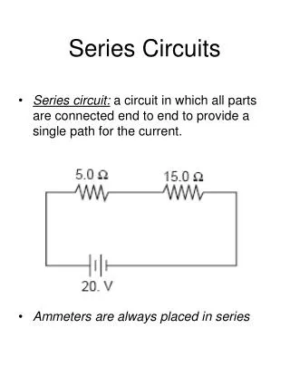
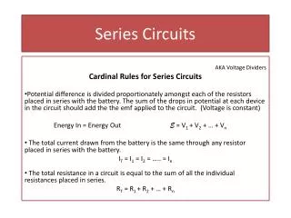
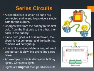
SERIES CIRCUITS (4) • Series connection of two resistors: • Prove the series resistance expression using the equivalent concept.
For the two resistors case, the voltage divider rule is: In general, for any number of resistors, the voltage drop across any resistor may be found as: Voltage Divider Rule
Solve for power dissipated in any resistor in a series circuit
Ammeter Loading effect • Loading effect refers to those undesirable effects as a result of load insertion to a circuit. • When we use an ammeter to measure to measure the current of a circuit, the ammeter is inserted into the circuit in SERIES. • The ammeter will have a small resistance, Ra, this will alter the current to:
Potential difference • Potential difference (p.d.) (unit in volts) • P.d.is a voltage gradient between any two points in a circuit. (Current flows from high to low potential level) • P.d. across a passive component is called a voltage drop • P.d.s across R1 and R2 are the same (i.e. V1=V2) • Voltage at A (Vs) is twice voltage at B (V2) • P.d. is a vector quantity (mag. & direction) • P.d. is a relative magnitude • P.d. is always across two points • 0 volt is typically chosen as the reference voltage for a system or circuit.This is referred to as the GROUND.
Example of incorrect grounding technique One of the input of the voltmeter is grounded, an attempt to measure the non-grounded voltage between points A and B of the circuit results in short-circuiting point B to ground. The voltage value measured will be erroneous.


![[Series Circuit]](https://cdn1.slideserve.com/2747272/series-circuit-dt.jpg)