Download
1 / 32
320 likes | 413 Views
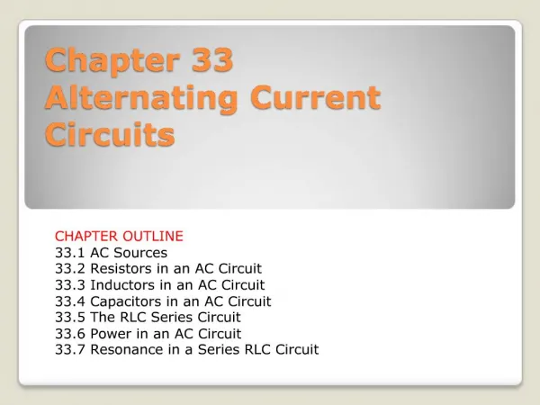
5. Alternating Current Circuits. 5.1 AC source characteristic 5.2 Resistor R in an AC circuit 5.3 Inductor L in an AC circuit 5.4 Capacitor C in an AC circuit 5.5 RLC series in an AC circuit. 5.6 Resonance in a series RLC circuit. How produce AC current. Some ways for AC generation.

E N D
5. Alternating Current Circuits 5.1 AC source characteristic 5.2 Resistor R in an AC circuit 5.3 Inductor L in an AC circuit 5.4 Capacitor C in an AC circuit 5.5 RLC series in an AC circuit. 5.6 Resonance in a series RLC circuit
5.1 AC Sources Characteristics An AC circuit consists of electric elements ( Resistor, capacitor and inductor) and power source that provides an alternating voltage This time- varying voltage is described by where ΔVmax is the maximum output voltage of the ac generator or the voltage amplitude Is the angular frequency which given by Where is the frequency of the generator (the voltage source) and T is the period.
We study the behavior of the electric elements R or L or C or RLC series in a AC circuit Inductor L Resistor R Capacitor C • Want to known: • The equation of Current • The phase angle ( )between V&I • The power energy P • Root mean square value (rms) RLC series
5.2 Resistor R in an AC Circuit Consider a AC circuit consisting of a resistor R and AC source By used Kirchhoff’s loop rule the instantaneous current iRin the resistor is the instantaneous current iR in is
Phase diagram of resistor R in AC circuit We conclude that the current iR and the voltage R across the resistor R The graph shows the variation current and the voltage across the resistor with time The current and the voltagereach their maximum values at the same time. So we say the current and the voltage are in phase i.e. =0 Current and Voltage in phase
Root mean square (rms) value of current (rms ) and voltage (Vrms) Average power delivered to a resistor
From the equation we have Vmax = 200 V Thus , the rms voltage Therefore and max= rms x 2 = 1.41 x 2 = 2 A
5.3 Inductors L in AC Circuit Consider an AC circuit consisting an inductor connected to AC source From EMF () across the inductor L= L=-L(di/dt)then apply Kirchhoff`s loop rule, we have + L = 0
We know cos t = - sin (t-/2) The current of inductor is OR where XL is the inductive reactanceالمعاوقة الحثية Root mean square values
Phase diagram of L in an AC circuit The current lags behind the voltage by 90°. The current lags behind the voltage by 90°. التيار يتاخر او يتخلف عن الجهد بزاوية مقدارها 90 درجة (¼دورة)
EX: In a purely inductive ac circuit, L = 25 mH and the rms voltage is 150 V. Calculate the inductive reactance and rms current in the circuit if the frequency is 60 Hz.
Ex: An ac power supply produces a maximum voltage Vmax= 100 Volt. This power supply is connected to a 24 resistor as figure. What is the rms current and rms voltage EX: An inductor has a 54 reactance at 60 Hz. What is the maximum current when this inductor is connected to a 50 Hz source that produce a 100 V rms voltage
5.4 Capacitor C in an AC Circuit Consider an AC circuit consisting an capacitor connected to AC source The current in a capacitor
The maximum current across the capacitor is OR Where the capacitive reactance XC is Root mean square values
Phase diagram of C in an AC circuit التيار يتقدم على الجهد بزاوية مقدارها 90 ( ¼ دورة)
5.5. The RLC series in an AC circuit Consider AC circuit consist of Resistor R , inductor L and capacitor C are connected in series The instantaneous applied voltage is And the instantaneous current is Where is the phase angle between the current and the applied voltage
The impedance Z of the circuit is Phase angle • is positive when XL >XC • is negative when XL < XC • is zero when XL =XC
(E). Calculate the average power delivered to the RLC series circuit From
5.6 Resonance in series RLC Circuit The resonance frequency ω 0of a series RLC circuitoccurs at XL-XC = 0 i.e (maximum current and Z=R ) . So the angular resonance frequency 0 is The resonance frequency f0 is