Download
1 / 12
120 likes | 150 Views
EVM Specification for OOK Waveform. Date: 2019-04-12. Authors:. Introduction. EVM (Error Vector Magnitude) is a typical metric for measuring transmit modulation accuracy For OFDM signal in 11a/n/ac/ad/ax, the EVM is measured for QAM symbols in frequency domain [1][2]

E N D
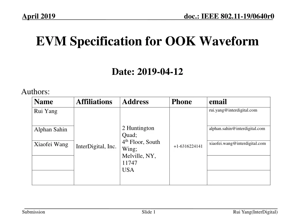
EVM Specification for OOK Waveform • Date: 2019-04-12 Authors:
Introduction • EVM (Error Vector Magnitude) is a typical metric for measuring transmit modulation accuracy • For OFDM signal in 11a/n/ac/ad/ax, the EVM is measured for QAM symbols in frequency domain [1][2] • For .11ba, a new formulation may be needed to measure the EVM for OOK symbols in time domain
EVM for OFDM Signal • Typically assuming certain capabilities and accuracies for the testing instrument: • Capable of converting the transmitted signal into a stream of complex samples • I/Q amplitude and phase balance • DC offset • Phase noise mitigation • Synchronization in time • Need to consider • Power normalization • Ideal symbol values (Copied from [1])
EVM for OOK Signal • Assumptions • Measured signal is normalized with average power • The testing equipment is capable of converting the transmitted signal into a stream of complex samples and measuring the magnitude of samples and accumulate them over On and Off durations Measurement “Off” “On” Envelope 0 EVM Normalized “Constellation” of OOK modulation Envelope Measured Samples On Off Time
EVM for OOK Signal (cont.) • Testing Requirements • Sampling rate: • During the test, a bandpass filter of which the 3dB-bandwidth is equal to [50.5] MHz shall be used to obtain the signal on the channel under the test. • The test shall be performed over at least [20] frames (). • Perfect synchronization • The frame under test, which includes both Sync and HDR/LDR data fields, shall be at least [256]s long. L-preamble L-preamble WUR Sync WUR Sync WUR Data WUR Data Test Frame Test Frame 1 . . . . . . .
Some Notations • : Number of tested frames in a measurement duration • : Number of On symbols in k-th test frame • : Number of Off symbols in k-th test frame • : Number of samples in On or Off symbol duration (assuming it is the same for both On and Off symbol durations), which is different for 2ms and 4ms symbols • is the i-th observed sample of signal envelope on the j-th On symbol and the k-th test frame; • is the i-th observed sample of signal envelope on the j-th Off symbol and the k-th test frame
Some Notations (cont.) • : the normalization factor of the received signal in a measurement duration • Note: • Assuming the testing instrument can obtain the real (I) and imaginary (Q) components of the WUR signal, the envelope functions in On symbol and in Off symbol may respectively be expressed as • and • where • , are the -th observed real and imaginary values in the -th On symbol and the -th test frame, respectively; • , are the -th observed real and imaginary values in the -th Off symbol and the -th test frame, respectively;
Some Notations (cont.) • Some options to define the “envelope”: • (the ones for “Off” symbols can be defined in the same way) • Which one should be used in the spec is TBD
EVM Expression • Defined normalized sample average for On and Off Symbols: • Then, the averaged RMS of WUR portion of all test frames is |I|+|Q| Time Normalized Eye Diagram
Simulation • Settings • Fs: 80 MHz • Nonlinear PA: Rapp model, 9dB back-off • ADC model: Kaiser filter where beta = 0.5 • RX filter: 5th order 5 MHz Butterworth • Options for defining the “envelope”
Simulation Results • Propose using as the reference • Propose requirement: EVM(HDR)= -20 dB, EVM(LDR) = -15 dB
References • [1] IEEE P802.11REMmd “Part 11: Wireless LAN Medium Access Control (MAC) and Physical Layer (PHY) Specifications”, 2019 • [2] “IEEE P802.11ax™/D3.0, Amendment 6: Enhancements for High Efficiency WLAN”, 2018 • [3] IEEE P802.11ba/D2.0, 2019 • [4] Alphan Sahin, et al., “OOK Waveform for FDMA”, IEEE 11-18/0682r2, 2018