Download
1 / 29
300 likes | 525 Views
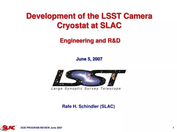
Development of the LSST Camera Cryostat at SLAC Engineering and R&D June 5, 2007. Rafe H. Schindler (SLAC). CRYOSTAT ASSEMBLY: Reference Design as of Aug 2006. Front flange for mounting for L3 Flange . Bosses on GRID for Raft Kinematic Mounts. Copper feedthrus. Fiber-optic feedthrus.

E N D
Development of the LSST Camera Cryostat at SLAC Engineering and R&D June 5, 2007 Rafe H. Schindler (SLAC)
CRYOSTAT ASSEMBLY: Reference Design as of Aug 2006 Front flange for mounting for L3 Flange Bosses on GRID for Raft Kinematic Mounts Copper feedthrus Fiber-optic feedthrus 3X GRID Z flexures Rear Access Plate Double O-rings at Plate mount Vacuum-jacket penetration for cryogen lines FP Fast Actuators GRID Cryo Plate for FEE cooling Back flange supports Feedthru Flange and cyl. mount Cold Plate for BEE cooling Cryostat and Valve Box Section view from front side
OUTLINE • ENGINEERING and R&D GOALS FOR 2007 • Cryostat Mechanical Design • Develop/Formalize Cryostat Interface Definitions • Advance “Baseline Design” – verify critical features with detailed analysis • Material Trade Studies For Long-Lead Time Elements (GRID) • Contamination Control • Construct Material Qualification & Test Facility (MQTF) To Evaluate Preparation and Impact of Materials Deployed in The Cryostat • Develop Contamination Control Plan • Metrology • Evolve The Focal Plane Alignment Concept • Prototype Critical Features of Raft-GRID Kinematic Interface • Prototype Performance of Non-Contact Metrological System for Camera Assembly • Study of In-Situ Metrology [Won’t Discuss Today]
CRYOSTAT SUBSYSTEM & IT’S MAJOR PHYSICAL INTERFACES CRYOSTAT SUBSYSTEM CONTAMINATION CONTROL INTEGRATION & TEST FRONT VAC FLANGE INSTRUMENT’N RING CRYOSTAT BODY REAR VAC. , SIGNAL , FLUID FLANGE GRID GRID FLEXURES & KIN MOUNT Camera Body Utilities Trunk Thermal System Vac. System Purge System Controls L3 Raft Tower Vac System Thermal Sys. Raft Tower FE 55 Source Diff. Pat. Gen. Controls BEE Thermal Sys. Vac. System Controls Raft Tower Guider/WFS Corner Raft Metrology Sys. Thermal Sys. Controls CRYO PLATE COLD PLATE COOLANT XFER LINES (2X) SHROUD Legend ELEMENTS OF CRYOSTAT Raft Tower Guider/WFS Thermal Sys. Controls BEE Thermal Sys. Controls Vac Sys. Thermal Sys. Controls Raft Tower Vac Sys. Thermal Sys. Controls MECHANICAL, ELECTRONIC, THERMAL OR OTHER INTERFACES
DEFINING / FORMALIZING CRYOSTAT INTERFACES • 2 DAY FACE TO FACE MTING AT SLAC IN MID-MAY TO DISCUSS MAJOR CRYOSTAT INTERFACE ISSUES WITH SENSOR & RAFT-TOWER GROUPS • RESULTED IN START OF RAFT CRYOSTAT INTERFACE DOCUMENT INCLUDING: • RAFT – GRID ENVELOPES • THERMAL LOADS (FEE & BEE) • FOCAL PLANE METROLOGY (METHODOLOGY & XFER OF REFS) • ELECTRONICS FEETHRUs EXAMPLE: RAFTGRID STAY CLEAR DOCUMENT
CRYOSTAT ENGINEERING: ADVANCING THE BASELINE DESIGN • L3 lens and flange structural analysis • Re-analyzed L3 to verify its ability to carry a vacuum load • Detailed analysis of temperature gradients across L3 and accompanying distortion • Cryo Plate structural analysis • Verify plate can carry spring & inertial loads of RAFT with little deflection • Cryostat Body design changes • Cylinder flared frustrum with in-line flange— • Came out of lens motion sensitivity analysis showing back flange + support ring not stiff enough reduced local rotations of focal plane by 2X; • GRID & Flexures Design Changes : • Elimination of Fast Actuators created GRID shear stiffness (bookshelfing) problem • Change GRID (& Cryoplate) shape from octagons to round & add stiffening elments • Change GRID Flexures to “A” Frame – reduces tip/tilt sensitivity of Focal Plane • Complete stress and buckling analyses (see example) L3 X-Section
Cryostat Housing Structural Design Change Flared housing provides more radial space for feedthrough plate Cryostat housing tapers back to an in-line flange One-piece support housing and Utility Trunk forward section increases mounting stiffness
EVOLUTION OF GRID, FLEXTURES, COLD PLATE DESIGN Flexures attach at 2 points on the Grid to distribute loads; Pre-mounted & inspected off three points prior to insertion & mounting to support flange Round GRID With Features for A-Flexures and Closed Plates Around Perimeter for Shear Stiffening Original Octagonal GRID With Features for 8 Fast Actuators and 3 Z-Flexures Thermal Shroud Round Cryo Plate
Material & Manufacturing Trade Studies For GRID • Silicon Carbide remains material of choice for GRID because of its stiffness, high thermal conductivity, low thermal expansion coef. & vac. friendliness • GRID material and manufacturing trade study being conducted in conjunction with detailed FEA for the design of the GRID • Identified numerous prospective SiC manufacturers • SSG • POCO Graphite • Coorstek • Cercom • Ceradyne • ECM • IBCOL (Germany) • M-Cubed • Xinetics • McCarter, Morgan Advanced Ceramics, Saint-Gobain, Trex, Kyocera, … • Identified other viable candidate materials • High-nickel alloys: Invar-36, Nilo, AL-36 • Beryllium alloys: O-30H • Beryllium metal matrix composites: E-60, AlBeMet 162H GRID Fabrication is a Long Lead Time Procurement - Likely to Require Vendor R&D OngoingDiscussions With Three Vendors Each Have Different Processes, Finishes, Max-Size & Dimensional Tolerance Capabilities --- LINKED TO STRUCTURAL ANALYSIS---
EXAMPLE: DRUMHEAD & SHEAR DISTORTION OF SiC GRID Flexure Location Flexure Location Flexure Location Flexure Location Flexure Location Gravity Flexure Location Gravity Maximum z displacement -2mm Maximum shear displacement -2.9mm Camera Coordinate System Camera Coordinate System • Finite Element Analysis of GRID Displacements under gravity • Includes Load of Raft-Towers • Example: Assume SiC [CESIC] with E = 249 GPa, n=0.17 r = 2700 kg/m3
CONTAMINATION TEST CHAMBER (MQTF) • FEE & cables (at the minimum) need to located within the Cryostat to achieve desired camera performance. They represent a significant surface area of non-vacuum friendly materials in close proximity to cold CCD’s of the FPA. • In addition to pumping, baffling (reducing molecular flow), & temp. control of gettering surfaces • developing protocol for material selection, processing & assembly to mitigate the long term contamination risk to the FPA. • also reviewing feasibility of removing BEE from cryostat • Early Development of Three Contamination Test Chambers (MQTF) allow: • study of material preparation (vacuum bakeout) in the 1st chamber • measuring outgassing (rates + species) and deposition of condensable films onto cold surfaces (thickness + species) in the 2nd chamber • measuring transmission vrs l thru condensable films (cold) in 3rd chamber INFORMATION NEEDED EARLY TO ALLOW DESIGN TO PROCEED • Once a material & preparation procedure is “qualified” • can define “minimal” tests assuring components prepared in this fashion, meet final requirements before I&T
CONTAMINATION TEST CHAMBER IN Bld-33 (Clean Room) Sample Preparation Chamber Outgassing Analysis Chamber Optical Transmission Chamber Main Chamber MAIN ANTE FORE Sample Entry Straight-Thru Valve Straight-Thru Valve Fore or Preparation Chamber cold finger Linear Manipulators & WS, RGA, QCM, Gas sys., Ion pump not shown Scroll & Turbopump Funded Thu R&D Program SLAC (+ beg, borrow, (steal)) ~ 3 mo. for bakeout & commissioning in Bld-33 Then Move to Campus Lab
3rd OPTICAL TRANSMISSION CHAMBER and OPTICAL TEST SETUP Squat To Reduce Light Path Optical Setup Being Tested in Lab 30cm cold finger Contaminated & Reference Samples Moved (Cold) From 2nd Chamber White Light Window Filter Wheel (LSST) Cold Sample Slide/or Uncontaminated Slide Window Precision Photodiode/PM. Piston Moves Samples Back & Forth In Vacuum Through Same Optical Path to Chop Measurements (Average Out Instabilities in Light Output) Expect <0.1% sensitivity: comparable to photometric target
FOCAL PLANE FLATNESS / METROLOGY • REQUIRE ~10 mm (P-V) FLATNESS ACROSS FPA • FOCAL PLANE BUILT UP OF THREE STRUCTURES • SENSORS (~5.0mm P-V) • RAFTS OF 9 CCD (~6.5mm P-V) • GRID OF 21 RAFTS (~10.mm P-V) • STRATEGY: BUILD PRECISION INTO GRID & RAFTS IN ADVANCE TO ALLOW A “SNAP TOGETHER ASSEMBLY” – ENGINEER IN RATHER THAN CALIBRATE OUT • Make GRID a Passive Structure Both Mechanically & Thermally • Choice of SiC For Stiffness & Conductivity & Thermal Exp. • Thermally Isolate To Minimize/Control Heat Flow & Distortion • Make Rafts Interchangeable Without Further Adjustment • Use a three-vee kinematic couplings with sub-mm repeatability • Setup all rafts relative to their kinematic mounts on same fixture • Pre-adjust Kinematic Mounts on Grid To Accept Master Raft Actual Errors More Complex – eg: See Accompanying Slide
PRELIMINARY ANALYSIS OF FOCAL PLANE FLATNESS ERRORS ±3s Errors SENSOR + RAFT (7.2mm) GRID (2.6mm) DYNAMIC (6.2mm)
RAFT TO GRID KINEMATIC MOUNT CONCEPT RAFT WITH SENSOR PKG, T-STRAPS, CABLES EMPTY Al Nitride RAFT PLATE INTEGRAL VEE BLOCKS SENSOR MOUNT & ALIGNMENT STUDS (3x) SiN BALLS, SiC BOSSES & SS CLIPS GRID GRID BAY
Raft Metrology Fixture Embodies Desired Geometry Needed at Focal Plane Array Raft & GRID Metrology Strategy To Simplify I&T Raft Metrology Fixture FEE Cage AT BNL Raft Flat and parallel to 3 balls ~100 nm Set up detectors coincident to the flat reference surface of the fixture
Cold Plate Cold Plate FEE Cage GRID GRID Raft A “Master Raft Fixture” transfers the Raft Metrology Fixture’s geometry (at BNL) to The GRID(at SLAC)Raft Kinematic Mounting Points On GRID Are Measured/Adjusted to Mimic Raft Metrology FixtureIn Advance of LoadingMotion Stage Used to Lift Master Raft Fixture Onto GRID Controlling Mating Points on Individual Kinematic MountsDuring Focal Plane Assembly, Same Stage Lifts Raft Onto the Same Kinematic Mating Points On GRID From BehindMetrological Verification Follows Immediately By Differential Non-Contact System Raft & GRID Metrology Strategy To Simplify I&T AT SLAC….
KINEMATIC MOUNT PROTOTYPE FOR RAFT-GRID • METROLOGY STRATEGY PREDICATED ON USE OF 3-Vee KINEMATIC COUPLINGS TO PROVIDE SUB-mm REPRODUCABILITY OF THE RAFT-GRID INTERFACE • LITERATURE SHOWS THAT COUPLINGS ARE SUITABLE BUT REQUIRE A BIT OF “ENGINEERING ART” – ON A CASE BY CASE BASIS…… SENSITIVITY TO: • Bulk material properties (stiffness and bearing strength) • Surface condition (finish and friction) • Shape of vee (wall angles, slotting, arching) • Mating (controlling mate-up) • Axial Stiffness (limited) • R&D FOR RAFT-GRID KINEMATIC COUPLING TO VERIFY PERFORMANCE • Developing Prototype Program In conjunction with GRID material trade study: • Find Best Geometry, Materials and Surface Preparations • Measure: • Variability from GRID Fabrication (one Raft on many Ball sets) • Repeatability of individual mounts (one Raft on one Ball set) • Interchangeability (many Rafts on one Ball set) • Temporal Stability of individual mounts • Thermal Stability / Hysteresis of individual mounts
KINEMATIC COUPLING PROTOTYPE R&D 10” Dewar Window (not shown) Raft Plate Raft Plate Assembly with Vee-Blocks Interchangeable Vee-blocks A286 ss, 6Al4V Ti, SiC Inconel 718. Misc. coatings (Nedox, DLC) for friction & hardness. ~16 min roughness Raft Plate Kinematic Coupling Prototype Parking Balls Reference Surfaces 2ND Ball Set Interchangeable Vee-blocks – angle and/or shape Silicon-nitride CL 5 Ball (round to 5min, smooth to 0.8 min rms) Base Mount with Flexure supports off the flange Epoxy Insertion Cold straps Test dewar Kinematic coupling interface Ball-and-Cup Assembly (2X3) Section View of Raft Plate & Base Mount
Dual sensor XY carriage Displacement sensors look up & down To Optical Flat and FPA (summing signal to remove carriage effects) Inspection Opt. Table Assy Opt. Table Reference surface XY carriage R&D To Verify Metrology System Concept for FPA Assembly Strategy:Measure Flatness of Focal Plane Using a Pair of Commercial Laser Displacement Sensors, Optical Stage, and a Smaller Reference Flat Stitch The Entire Surface Together By Measuring Multiple Overlapping Regions (each ~RAFT Size) Bottom view shows partial buildup of focal plane Camera focal plane surface
DEMONSTRATION OF DIFFRENTIAL NON-CONTACT METROLOGYSYSTEM IN AIR XY STAGE TO MOVE LASER HEADS l/10 OPTICAL FLATS UP & DOWN LOOKING LASER DISPLACEMENT HEADS XY
DEMONSTRATION OF NON-CONTACT SYSTEM IN AIR • Measure Differential figure between two λ/10 flats • Scan over 200mm diameter (300 points) takes 600 seconds • Sensor Non-Linearity correction applied • Computed figure is < 0.4um P-V over 200mm diam. surface with better than 0.1um repeatability SCALE OF RAFT Next Step: To Repeat Through Vacuum Window & Cold
CONCLUSIONS • ENGINEERING PROCEEDING ON CRYOSTAT DESIGN – • UPDATING/DETAILING DESIGN WITH FINITE ELEMENT ANAL IN CRITICAL AREAS • DESIGN AND ANALYSIS COUPLED TO MATERIALS SELECTION STUDIES • CRITICAL INTERFACES BEING DEFINED (esp. RAFT-TOWER to GRID) • THERMAL ANALYSIS “ON HOLD” THIS YEAR FOR BUDGETARY REASONS • TOOLS FOR CONTAMINATION STUDIES UNDER CONSTRUCTION • DEVELOPING MATERIALS TEST FACILITY -- CONSTRUCTION ADVANCING WELL • OTHER IMPROVEMENTS TO DESIGN BEING CONSIDERED TO FURTHER MITIGATE RISK • METROLOGY CONCEPTS HAVE MATURED • OVERALL CONCEPT FOR FOCAL PLANE ASSEMBLY HAS BEEN DEFINED • PROTOTYPE KINEMATIC MOUNT FOR RAFT ALIGNMENT ON GRID BEING TESTED AT SLAC • TESTS OF CONCEPT TO ALIGN SENSORS ON RAFTS TO BE CONDUCTED AT BNL • PROTOTYPE METROLOGY SYSTEM FOR FULL FPA ASSEMBLY TESTED SUCCESSFULLY IN AIR – SETTING UP FOR VACUUM/COLD TEST
EXTRA SLIDES • EXTRA SLIDES
Demonstrated fidelity is adequate for FP metrology feedback Leitz PMM 12106 (CMM) advertised standard & high (volumetric) uncertainties U3 for 120mm translation calibration limit (flatness of reference surfaces)
Stitching Metrology Checkout • Detector surface figure measurement fidelity depends upon the tradeoff imposed by measurement rapidity vs. completeness. • We have shown that simulated, bootstrap surface figure measurements provide quatifiable error propagation for specific sets of measurement grid, reference grid and reference shape definitions.
Parasitic derivation of nonlinearities in each displacement sensor • LK-G32: 50 μm period, 1.5 μm P-V • LK-G15: 10 μm period, 0.35 μm P-V