Download
1 / 17
170 likes | 399 Views
Task 2, November update Time variation and modal noise study. Participants and supporters Robert Coenen David Cunningham John Dalessasse Piers Dawe Jens Fiedler Ali Ghiasi Pete Hallemeier Jesper Hanberg John Jaeger Jonathan King. Paul Kolesar Brent Whitlock Tremant Maio

E N D
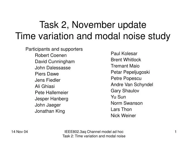
Task 2, November updateTime variation and modal noise study • Participants and supporters • Robert Coenen • David Cunningham • John Dalessasse • Piers Dawe • Jens Fiedler • Ali Ghiasi • Pete Hallemeier • Jesper Hanberg • John Jaeger • Jonathan King Paul Kolesar Brent Whitlock Tremant Maio Petar Pepeljugoski Petre Popescu Andre Van Schyndel Gary Shaulov Yu Sun Norm Swanson Lars Thon Nick Weiner IEEE802.3aq Channel model ad hocTask 2: Time variation and modal noise
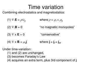
Task 2 goals Study the impact of time varying effects on the LRM spec • Provide input to the TP3 time varying component of the receiver compliance test • Set a frequency below which EDC should track (TP3 test rate) and/or • Define tracking 'mask' - size vs frequency of perturbation • Define spectrum/extent of time variation effects • Mechanical vibration environment • Modeling of extent of time variance of links • Effect of temperature on link components • Study of modal noise of the MMF channel • Assess modal noise penalty for different laser types IEEE802.3aq Channel model ad hocTask 2: Time variation and modal noise
Task 2 Progress • Agreed test configuration for modal noise modeling and experiments • Referencing GR-63-CORE for operational vibration testing • describes vibration tests for in-building environment at constant acceleration, (0.1g & 1g) from 5-100 Hz (vibration amplitude ~1/f2) • Study of temperature effects • Comprehensive list of mechanisms compiled and size of each effect determined Most temperature effects are not an issue • Vibration tests to determine relationship of mechanical perturbation frequency to impulse response variation • experiments at 10-100Hz, 1g acceleration (referencing GR-63-CORE) • frequency multiplication observed, greatest effect at fundamental • max freq of interest 24Hz, for 'just noticeable' level of data envelope modulation • lower frequencies for more larger channel effects • Quasi-static Impulse Response measurements: • Polarisation effect - experiment shows it has similar effect on channel as multimode fibre perturbation • Input patch cord shaking experiments show worst case 10Hz 'best to worst' impulse response evolution • Modal noise calculations adapted for equalized links in order to include noise enhancement, supports 0.5dB maximum penalty allowance IEEE802.3aq Channel model ad hocTask 2: Time variation and modal noise
Polarization controller main fibre TP2 TP3 Tx Rx C0 C1 C2 C3 10m perturbed fibre 2m patchcord Offset jumper 1) Test configuration for modal noise modeling & measurement • To maximize modal effects, the 2 multimode connectors closest to the transmitter were chosen to have maximum offset. • C3 connection set to a lower loss condition to avoid exceeding connector loss budget. • Vibration of connectors is not expected to affect offsets • It is only required that the first length of fibre between C1 and C2 is shaken IEEE802.3aq Channel model ad hocTask 2: Time variation and modal noise
2) Vibration tests representing office environment Referencing GR-63-CORE • Bellcore standard describing test conditions for telecomms central office equipment in a controlled indoor environment • Describes vibration tests at constant acceleration (0.1g & 1g) from 5-100 Hz • Vibration amplitude ~ 1/f2 • 0.1g acceleration at 1Hz corresponds to a 25mm perturbation amplitude this is similar to TIA/EIA-455-203 fibre shaker • 1g acceleration at 1Hz corresponds to 250mm amplitude - similar to vigorous manual shaking of a fibre coil • 1g acceleration at 1kHz corresponds to 0.25micron amplitude - very small ! Suggests that low frequency range are the test case of interest ref: king_1_0904 IEEE802.3aq Channel model ad hocTask 2: Time variation and modal noise
3) Temperature variation impact Interim findings given in Popescu_02_0904 (September Interim meeting) • Impact of temperature change on receiver, main fibre and most transmitter laser parameters found to be small enough to ignore Recent progress • Micro-bend losses can be induced by two temperature dependent mechanisms (humidity penetration and the differing thermal expansion coefficients of the silica fiber and most plastics, see popescu_2_0904). These effects occur at low temperature, below the 0 deg. C, outside the nominal operating range. Remaining link related items • Impact of polarization change due to connector temperature variation and impact on modal noise, work in progress following results from task 4. Remaining LRM spec related items • Limits for laser mode-partition noise over operating temperature range and impact on modal noise, work in progress following results from task 2 and TP2. • Laser relaxation oscillation and damping variation over operating temperature range and impact on jitter generation and jitter tolerance, work in progress following results from task 2 andTP2. IEEE802.3aq Channel model ad hocTask 2: Time variation and modal noise
carrier+7Hz 5GHz carrier 4) Vibration Testing 1: Set up & example spectrum Ref: 'Time variance in MMF links - further test results', Rob Coenen • A 10m MM fiber coil was suspended vertically (noted to be worst case) and mechanically shaken at various frequencies between 6 and 30 Hz. Mechanical vibration modulation sidebands on a 5GHz optical tone were recorded • Received signal spectrum for 7Hz vibration, 1g acceleration • Sidebands at 7, 14, 21 and 28Hz from signal tone. • Sideband ratios are -21, -28, -30 -35dB IEEE802.3aq Channel model ad hocTask 2: Time variation and modal noise
4) Vibration Testing 2: Sideband level vs frequency • Magnitude of channel variation drops rapidly with frequency • Amplitude of physical movement of the fiber dictates the magnitude of the channel variations (not the rate at which it is moved). • Effect of the 1st harmonic dominates over higher order harmonics Conclusions • Maximum channel variation frequency is < 40 Hz, due to the 1st harmonic. The max channel variation frequency due to the 2nd harmonic is ~24Hz. • For larger channel variations the maximum frequency is lower, the absolute amount depending upon the channel in question IEEE802.3aq Channel model ad hocTask 2: Time variation and modal noise
5) Quasi-static impulse response measurements 1 Ref: 'Experiments on time-variation due to polarization and MMF shaking and results', Jonathan King (More detailed talk later in king_2_1104) • A polarisation scrambler, and single-mode and multi-mode fibre figure of 8 shakers were used at the input of a 300m MMF fibre, to study the effect of the polarisation effect and MMF perturbation on dynamic channel response A fibre and launch combination was selected to generate a 2 peaked impulse response with large IPR variation, and IPR evolution recorded • Polarization effect found to • explore similar (smaller) IPR space as thorough MMF fibre shaker ...... no new channel responses ! • power change in an IPR peak >> than mode selective loss • Quasi-static IPR evolution measurements • Synchronously driven SMF plus MMF shaker used to provide full IPR exploration • shrinks quasi static measurements to linear measurement domain • includes polarisation and MMF mode mixing effects • representative of a perturbed patchcord IEEE802.3aq Channel model ad hocTask 2: Time variation and modal noise
5) Quasi-static impulse response measurements 2Impulse response sequence Fibre and launch selected for study: 7um offset centre launch gave 2 peaked IPR Causal to symmetric to anti-causal IPR variation possible 180mm total Fo8 shaker movement IEEE802.3aq Channel model ad hocTask 2: Time variation and modal noise
SMF shaker only SMF + MMF shakers 5) Quasi-static impulse response measurements 3SMF + MMF shaker, vs SMF (polarisation effect) only • Causal to anti-causal evolution in 5mm shaker movement • Similar rate of IPR evolution for SMF shaker only (polarisation effect only) • Polarization effect explores subset of IPRs explored with MMF + SMF shaker • Following GR-63-CORE, equivalent to 10Hz vibration amplitude at 1g 5mm IEEE802.3aq Channel model ad hocTask 2: Time variation and modal noise
6) Modal Noise Ref: 'Improvements to Modal Noise Penalty Calculations', Petar Pepeljugoski et al (More detailed talk later) Modal noise theory has been adapted to better represent LRM applications and supports the 0.5dB maximum penalty allowance in the LRM link budget. • For OSL launch into 50 and 62.5um fibre, modal noise penalty is below 0.5dB for up to 17um and 25um offset launches respectively. • For a direct launch into OM3 fibres, modal noise penalty is below 0.5dB for an 86% encircled flux radius of up to 18um. This corresponds to <0.5dB modal noise penalty if total MSL through the link is <1.5dB More details in Pepeljugoski_1_1104 IEEE802.3aq Channel model ad hocTask 2: Time variation and modal noise
Summary 4) Vibration experiments • Low frequency vibration has most impact; 1st vibration frequency harmonic dominates, higher orders are less significant • 40 Hz is the estimated maximum rate at which any significant channel variations (-24dB sideband level) may occur under the office vibration conditions referenced in GR-63-CORE. Larger effects occur only at lower frequencies (-8dB at 10Hz) 5) Polarisation effect and quasi-static channel measurements • Similar impact on channel as fibre perturbation - no new channel responses ! • Not reliant on MSL: power variation of IPR peaks >>MSL of link • Note: similar findings for 3 independent experimenter groups • SMF + MMF fibre shaker experiments • similar IPR evolution rates vs displacement for SMF and MMF figure of 8 shakers • worst case IPR variation in 5mm shaker motion • would correspond to 10Hz vibration rate (GR-63-CORE) • suggests TP3 dynamic test rate of 10Hz for full IPR evolution 6) Modal Noise • theory adapted to LRM application • Shows 0.5dB modal noise penalty is conservative estimate of penalty IEEE802.3aq Channel model ad hocTask 2: Time variation and modal noise
Possible Task 2 recommendations to Task Force ? • Modal Noise Penalty • 0.5dB sufficient for LRM • Polarisation effect • does not introduce any new penalties • Can be included in dynamic adaption requirement under mechanical vibration of input patchcord to link • Impact of effect can be bounded by experiment • Dynamic test for TP3: • avoid 'path penalty' type measurement • allow greatest freedom of implementation • recommend adopting a dynamic adaption test with pass/fail based on BER<10-12 at maximum OMA in • Low frequency effects most significant • Adaption test (pass/fail) at 10 Hz rate • e.g. 2 peak 60:40 - 40:60 at 10Hz, following • or 3 peak as per TP3, with a=0.6 IEEE802.3aq Channel model ad hocTask 2: Time variation and modal noise
Further info IEEE802.3aq Channel model ad hocTask 2: Time variation and modal noise
Summary of temperature variation impact Ref: Popescu_02_0904 • Note 1: Temperature variation impact on time varying channel is small. • Note 2: Laser polarization change and mode-partition noise change over the operating temperature range and impact on noise need more analysis. IEEE802.3aq Channel model ad hocTask 2: Time variation and modal noise
Vibration experiment set up • A 10m MM fiber coil was suspended vertically (worst case) and mechanically shaken at various frequencies between 6 and 30 Hz. IEEE802.3aq Channel model ad hocTask 2: Time variation and modal noise