Download
1 / 70
830 likes | 1.18k Views
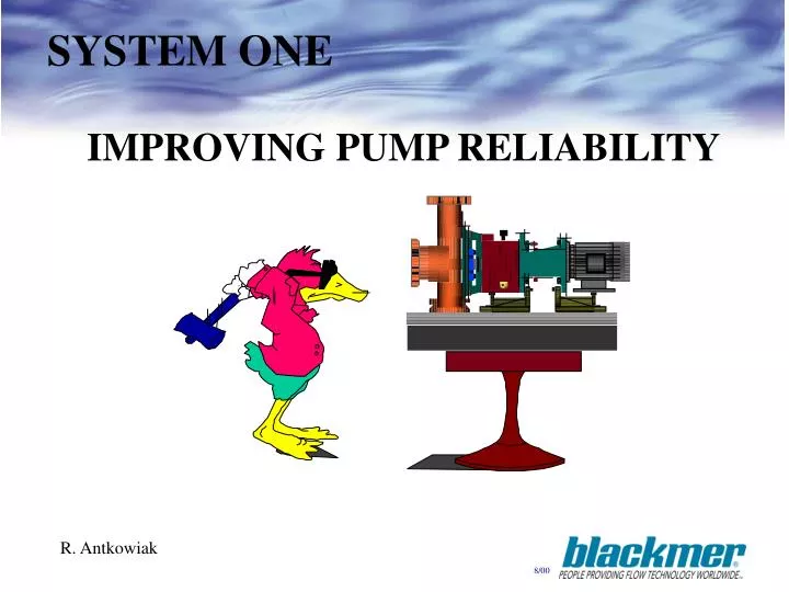
SYSTEM ONE. IMPROVING PUMP RELIABILITY. R. Antkowiak. Maintenance vs. Capital. What does a pump actually cost ? Most plants regard the pump as a commodity... purchased from the lowest bidder with little consideration for:

E N D
SYSTEM ONE IMPROVING PUMP RELIABILITY R. Antkowiak
Maintenance vs. Capital • What does a pump actually cost ? Most plants regard the pump as a commodity... purchased from the lowest bidder with little consideration for: • The operation and maintenance cost of the pump over its life cycle... which could be 20 - 30 years • Costs to be considered: • Spare parts (inventory costs) • Operation downtime (lost production) • Labor to repair (maintenance costs) • Power consumption based on pump efficiency • Environmental, disposal, and recycle costs
TRUE PUMP COSTS • Repair costs can easily exceed the price of a new pump (several times) over its life of 20 -30 years • Documented Pump failures cost $4000 or more per incident ( parts and labor) • If MTBF was improved from 1 to 2 years for a pump in a tough application • Results in savings of $2000 /year over the life of the pump
WHY PUMPS AND SEALS FAIL MECHANICAL Affects Bearings, Seals and Shafts -EXTERNAL 1. Operation off the BEP 2. Coupling Misalignment 3. Insufficient NPSH 4. Poor Suction and Discharge Piping Design 5. Pipe Strain / Thermal Expansion 6 Impeller Clearance 7. Foundation and Baseplate -INTERNAL 1. Pump Design and Manufacturing Tolerances 2. Impeller Balance (Mechanical and Hydraulic) 3. Mechanical Seal Design ENVIRONMENTAL Affects Wet End Components, Bearings and seals 1. High Temperature 2. Poor Lubrication / Oil Contamination 3. Corrosion 4. Erosion 5. Abrasion
HOW ARE FAILURES INITIATED? • Installation • Piping system & Pipe Strain • Alignment • Mechanical Seal installation • Foundation • Operational • System: cavitation, dry running, shutoff • Product changes: viscosity, S.G., temp. • Seal controls: flush, cooling • Misapplication • Pump, seal, metallurgy selection
RADIAL LOADOperation of a pump away from the BEP results in higher radial loads ...creating vibration and shaft deflection H E A D B.E.P FLOW
Radial Forces • By design, uniform pressures exist around the volute at the design capacity (BEP) • Resulting in low radial thrusts and minimal deflection. • Operation at capacities higher or lower than the BEP • Pressure distribution is not uniform resulting in radial thrust on the impeller • Magnitude and direction of radial thrust changes with capacity (and pump specific gravity)
Shaft Deflection • Most pumps do not operate at BEP: • Due to improper pump selection (oversized) • Changing process requirements (throttling) • Piping changes • Addition of more pipe, elbows and valves • System head variations • Change in suction pressure, discharge head req’d • Buildup in pipes • Filter plugged • Automatic control valve shuts off pump flow • Change in viscosity of fluid • Parallel operation problems (starving one pump)
PUMP SPECIFIC SPEED • CLASSIFIES IMPELLERS ON THE BASIS OF PERFORMANCE AND PROPORTIONS REGARDLESS OF SIZE OR SPEED • FUNCTION OF IMPELLER PROPORTIONS • SPEED IN RPM AT WHICH AN IMPELLER WOULD OPERATE IF REDUCED PROPORTIONALLY IN SIZE TO DELIVER 1 GPM AND TOTAL HEAD OF 1 FOOT • DESIGNATED BY SYMBOL Ns Ns = RPM(GPM)1/2 H3/4 RPM = SPEED IN REVOLUTIONS / MINUTE GPM = GALLONS /MINUTE AT BEST EFF. POINT H = HEAD IN FEET AT BEST EFF. POINT
PUMP SPECIFIC SPEED (Metric) • CLASSIFIES IMPELLERS ON THE BASIS OF PERFORMANCE AND PROPORTIONS REGARDLESS OF SIZE OR SPEED • FUNCTION OF IMPELLER PROPORTIONS • SPEED IN RPM AT WHICH AN IMPELLER WOULD OPERATE IF REDUCED PROPORTIONALLY IN SIZE TO DELIVER 1 M3/h AND TOTAL HEAD OF 1 M • DESIGNATED BY SYMBOL Ns Ns = RPM(M3/h) 1/2 M 3/4 RPM = SPEED IN REVOLUTIONS / MINUTE M3/h = CUBIC METERS PER HOUR AT BEST EFF. POINT MH = HEAD IN METERS AT BEST EFF. POINT
PUMP TYPE VS. SPECIFIC SPEED SI 10 20 40 60 120 200 300 US 500 1,000 2,000 3,000 6,000 10,000 15,000 HEAD EFFICIENCY HEAD, POWER EFFICIENCY HEAD, POWER EFFICIENCY HEAD, POWER EFFICIENCY POWER CAPACITY CAPACITY CAPACITY CENTRIFUGAL VERTICAL TURBINE AXIAL FLOW SPECIFIC SPEED, ns (Single Suction) RADIAL-VANE FRANCIS-VANE MIXED FLOW AXIAL FLOW
RADIAL FORCES ON IMPELLER BEP CUTWATER RADIAL LOAD 125% BEP 100% FLOW 50% % CAPACITY of BEP 150% SHUTOFF 0% Length of Line = Force
THE IMPORTANCE OF ALIGNMENT • Any degree of misalignment between the motor and the pump shaft will cause vibration in the pump • Every revolution of the coupling places a load on the pump shaft and thrust bearing • At 3500 RPM, there will be 3500 pulses per minute applied to the shaft and bearing
MISALIGNMENT • MAY BE CAUSED BY: • Pipe strain • Thermal growth • Poor foundation / baseplate • Improper initial alignment • System vibration / cavitation • Soft foot on motor
NET POSITIVE SUCTION HEAD (NPSH)One of the more difficult characteristics to understand • In simplistic terms: • Providing enough pressure in the pump suction to prevent vaporization of the fluid as it enters the eye of the impeller Two values to be considered: • NPSH available • Amount of pressure (head) in the system due to atmospheric or liquid pressure, height of suction tank, vapor pressure of the fluid and friction loss in the suction pipe
NPSHcont. • NPSH required • Pressure reduction of the fluid as it enters the pump • Determined by the pump design • Depends on impeller inlet, design, flow, speed and nature of liquid • NPSH available must always be > NPSH required by a minimum of 3-5 feet (1-1.5m) margin
CAVITATION • Results if the NPSH available is less than the NPSH required • Occurs when the pressure at any point inside the pump drops below the vapor pressure corresponding to the temperature of the liquid • The liquid vaporizes and forms cavities of vapor • Bubbles are carried along in a stream until a region of higher pressure is reached where they collapse or implode with tremendous shock on the adjacent wall • Sudden rush of liquid into the cavity created by the collapsed vapor bubbles causes mechanical destruction (cavitation erosion or pitting)
CAVITATIONcont. • Efficiency will be reduced as energy is consumed in the formation of bubbles • Water @ 70oF (20oC)will increase in volume about 54,000 times when vaporized • Erosion and wear do not occur at the point of lowest pressure where the gas pockets are formed, but farther upstream at the point where the implosion occurs • Pressures up to 150,000 psi have been estimated at the implosion (1,000,000 Kpa)
RELATIVE PRESSURES IN THE PUMP SUCTION E D B A C TURBULENCE, FRICTION, ENTRANCE LOSS AT VANE TIPS INCREASINGPRESSURE DUE TO IMPELLER ENTRANCE LOSS FRICTION POINT OF LOWEST PRESSURE WHERE VAPORIZATION STARTS INCREASING PRESSURE A B C D E POINTS ALONG LIQUID PATH
NET POSITIVE SUCTION HEAD AVAILABLE Hf • (frictionin suction pipe) PAtmospheric Z NPSH Available = P Atm. - Pvap. pressure - Z - Hf Correct for specific gravity All terms in “feet (meters) absolute”
High Temp. Rise Low Flow Cavitation Discharge Recirculation Low Brg . & Seal Life Reduced Impeller Life Suction Recirculation Head Head BEP BEP Low Brg . & Seal Life Cavitation Flow Flow Results of Operating Off BEP
TEMPERATURE RISE • Overheating of the liquid in the casing can cause: • Rubbing or seizure from thermal expansion • Vaporization of the liquid and excessive vibration • Accelerated corrosive attack by certain chemicals • Temperature rise per minute at shutoff is: • T oF (oC) / min.= HP (KW)so x K • Gal (m3) x S.G. x S.H. • HPso = HP (KW) @ shutoff from curve • Gal. (m3) = Liquid in casing • S.G. = Specific gravity of fluid • S.H. = Specific heat of fluid • Ex.: Pump w/ 100HP (75KW) @s.o. , 6.8 gal casing (.03m3) • w/ 60oF (16oC) water would reach boiling in 2 min. • A recirculation line is a possible solution to the low flow or shut off operation problems....
ROTATION 10 inches250 mm COEFFICIENT OF THERMAL EXPANSION FOR 316 S/SIS 9.7X10⁻⁶ IN/IN/°F OR 17.5 X10⁻⁶ MM/MM/°CCALCULATION IS T x 9.7 X10⁻⁶ X LENGTH IN INCHES T x 17.5X10⁻⁶ X LENGTH IN MILLIMETERS EXPANSION T° C T° F INCHES MILLIMETERS 100 F 55 C 0.0097 IN 0.245 MM 200 F 110 C 0.0190 IN 0.490 MM 300 F 165 C 0.0291 IN 0.735 MM 400 F 220 C 0.0388 IN 0.900 MM 500 F 275 C 0.0485 IN 1.230 MM 600 F 330 C 0.0582 IN 1.470 MM CASING GROWTH DUE TO HIGH TEMPERATURE
IMPELLER CLEARANCE • Critical for open impellers • Normal setting .015” (.38mm) off front cover • High temperature requires more clearance • - Potential rubbing problem causes vibration • and high bearing loads • - Set impeller .002” (.05mm) add’l clearance • for every 500 F(280C) over ambient temp. • Important for maximum efficiency
IMPELLER BALANCE • MECHANICAL • - Weight offset from center of impeller • - Balance by metal removal from vane • HYDRAULIC • - Vane in eye offset from impeller C/L • - Variation in vane thickness • - Results in uneven flow paths thru impeller • - Investment cast impeller eliminates • problem • - Careful machining setup can help
TYPICAL ANSI (or DIN) PROCESS PUMP • Small dia. shaft with excessive overhang • Stuffing box designed for packing • Shaft sleeve • Light to medium duty bearings • Rubber lip seals protecting the bearings • Snap ring retains thrust bearing in housing • Shaft adjustment requires dial indicator • Double row thrust bearing • Cast jacket on bearing frame for cooling • Small oil reservoir
ANSI (ISO/DIN) STANDARD PUMPS • Industry standards for dimensions based on • requirements for packed pumps • Shaft overhang a function of # packing rings • and space for gland and repack accessibility • Clearance between shaft and box bore based • on packing cross-section • If most pumps today use mechanical seals - • why do we continue to use inferior designs • made for packing ??
BEARING OIL SEALS • Rubber Lip Seals Provided To Protect Bearings in standard ANSI pumps • Have life of less than four months • Groove shaft in first 30 days of operation • External contamination causes bearing failure
LIP SEAL LIFE • AUTOMOBILE • 100,000 Miles @ 40 Miles /hr. = 2500 hrs. of operation • PUMP • 24 hrs./day x 365 days / year = 8760 hours • 60% of lip seals fail in under 2000 hours • Lip seals may be fine for automobiles, but not for pumps
THRUST BEARING SNAP RING • Thrust bearings in standard ANSI pumps are held in place with a snap ring • Snap ring material harder than bearing housing • Wear in bearing housing results in potential bearing movement • Difficult to remove and install • If installed backwards - potential loose bearing
Radial Thrust due to Impeller and Misalignment Impeller Radial Thrust Hydraulically Impeller Axial Thrust Induced Forces due to Recirculation & Cavitation Coupling Seal Axial Load from Misalignment and Impeller Radial Thrust due to Impeller and Misalignment Hydraulic Imbalance Motor SIMULTANEOUS DYNAMIC LOADS ON PUMP SHAFT
SHAFT DYNAMICS • Radial movement of the shaft occurs in 3 forms: • Deflection - under constant radial load in one direction • Whip - Cone shaped motion caused by unbalance • Runout - Shaft bent or eccentricity between shaft sleeve and shaft It is possible to have all 3 events occurring simultaneously • ANSI B73.1 and API 610 • Limit radial deflection and runout of the shaft to 0.002 T.I.R. at the stuffing box face(0.05mm) • Solid shafts are critical for pump reliability • Eliminate sleeve runout • Improved stiffness
PUMP FAILURE ANALYSIS6 month period in a typical process plant
OPTIMUM PUMP DESIGN • OBJECT: Create a better environment and greater stability for the dynamic pump components (seals and bearings) ….to withstand the damaging forces inflicted upon them
SHAFT STIFFNESS 500 Lbs. (225Kg) 500 Lbs. (225Kg)
Derivation of Stiffness Ratio P L D = Deflection of shaft P = Load E = Modulus of Elasticity L = Length of Overhang = PL3 I= D4 3EI 64 = PL3 = L3 3E P D4 D4 64 I = Moment of Inertia cancel all common factors
L 1.50" 8" L /D = 8 /(1.50) = 512/5.06 = 101 1.62" 8" L /D = 8 /(1.62) = 512/6.89 = 74 3 4 3 4 3 4 3 4 1.75" 8" L /D = 8 /(1.75) = 512/9.38 = 55 3 4 3 4 1.87" 8" L /D = 8 /(1.87) = 512/12.23 = 42 Stiffness Ratio Examples D D L 3 4 3 4
Stiffness Ratio Examples D L D L 3 4 3 4 1.87" 8" L /D = 8 /(1.87) = 512/12.23 = 42 3 4 3 4 L /D = 6 /(1.87) = 216/12.23 = 17 1.87" 6"
4 3 4 3 =200 / 38 = 8000000/2085136 = 3.84 38mm L /D 200mm 3 4 4 /D = 200 L 3/ 40 = 8000000/2560000 = 3.13 40mm • 200mm 4 3 4 3 /D = 200 / 45 =8000000/4100625 = 1.95 45mm 200mm L 4 3 4 3 /D = 200 / 48 = 8000000/5308416 = 1.51 L/D<2.0 is Adequate 48mm 200mm L Stiffness Ratio Examples D L D L
4 3 3 =200 / 48 = 8000000/5308416 = 1.51 /D4 48mm L 200mm 3 4 4 /D = 150 48mm • 150mm L 3 / 48 = 3375000/5308416 = .64 Stiffness Ratio Examples D L D L L/D < 2.4 Considered Adequate
LD PUMPS REDUCE BEARING LOADS A A = Radial load on thrust bearing 100 Lbs. B = Radial load on radial bearing 100 lb. = Impeller radial load on end of shaft 6 in. 8 in. Standard ANSI Pump B M =0=14(100)-6B 1400=6B B=233 lbs. A M =0= 8(100)-6A 800=6A A=133 lbs. B LD PUMP M =0=11(100)-6B 1100=6B B=183 lbs. A A M =0= 5(100)-6A 500=6A A= 83 lbs. 100 Lbs. B • Radial Bearing 233 lbs. To 183 lbs. 6 in. 22% Reduction in Load 5 in. 2.1 x Improvement in Life • Thrust Bearing B 133 lbs. To 83 lbs. 37% Reduction in Load 4 x Improvement in life Bearing rating life varies inversely as the cube of the applied load
LD PUMPS REDUCE BEARING LOADS(Metric) A A = Radial load on thrust bearing 45.4. Kg B = Radial load on radial bearing 45.4 Kg = Impeller radial load on end of shaft 152 mm 203 mm Standard ANSI (DIN/ISO) Pump B 16,117=152B M =0=355(45.4)-152B B=106 Kg A M =0= 203(45.4)-152A 9,216=152A A=61 kg B LD PUMP M =0=279(45.4)-152B 12,667=152B B=83 Kg A A M =0= 127(45.4))-152A 5,766=152A A= 38 Kg 45.4 Kg B • Radial Bearing 106 Kg To 83 Kg 22% Reduction in Load 152 mm 127 mm 2.1 x Improvement in Life • Thrust Bearing B 61Kg To 38 Kg 37% Reduction in Load 4 x Improvement in life Bearing rating life varies inversely as the cube of the applied load
MAXIMUM STIFFNESS RATIO • L3 / D4 RATIO • Less than 60 (Inch) • Less than 2.4 (Metric)
Length (L) Dia. (D) 150 155 160 165 170 175 180 185 190 195 200 205 210 215 220 225 230 235 20 21,1 23,3 25,6 28,1 30,1 33,5 14,4 22 15,9 17,5 19,2 21 22,9 25,9 25 8,6 9,5 10,5 11,5 12,6 13,7 14,9 16,2 5,1 30 4,2 4,6 5,5 6,1 6,6 7,2 7,8 8,5 32 3,2 3,6 3,9 4,3 5,1 5,6 6 6,5 7,1 7,6 4,7 35 2,2 2,5 2,7 3 3,3 3,6 3,9 4,2 4,6 5,3 5,7 6,2 4,9 38 1,8 2 2,2 2,4 2,6 2,8 3 3,3 3,6 3,8 4,1 4,4 4,8 5,1 1,6 42 1,1 1,2 1,3 1,4 1,6 1,7 1,9 2 2,2 2,4 2,6 2,8 3 3,4 3,7 3,9 3.2 45 0,9 1 1,1 1,2 1,3 1,4 1,5 1,7 1,8 2 2,1 2,3 2,4 2,6 2,8 3 0,8 3.2 48 0,70 0,77 0,85 0,92 1 1,1 1,19 1,29 1,4 1,51 1,62 1,74 1,87 2, 2,15 2,29 2,44 0,65 2,08 50 0,54 0,60 0,66 0,72 0,79 0,86 0,93 1,01 1,10 1,19 1,28 1,38 1,48 1,59 1,70 1,82 1,95 55 0,37 0,41 0,45 0,49 0,54 0,59 0,64 0,69 0,75 0,81 0,87 0,94 ,01 1,09 1,16 1,24 1,33 1,42 ZONE 1= POOR >3.2 ZONE 2 = QUESTIONABLE 2.4-3.2 System one LD 17 ZONE 3 = EXCELLENT 1.0-2.4 ZONE 4 = SUPERIOR <1.2 • STIFFNESS RATIO CHART - METRIC
ZONE L3/D4 INCH A > 80 B 60 > 80 C 26 > 60 D < 26 > 3.2 B 2.4 to 3.2 C 1.0 to 2.4 D < 1.0 EFFECTIVE PUMP OPERATIONAL ZONES PUMP CURVE BEP A HEAD B METRIC A C D 80 40 20 10 0 10 20 15 25 PERCENT OF BEP FLOW
ALIGNMENT • EVERY TIME A PUMP IS TORN DOWN, THE MOTOR SHAFT AND PUMP SHAFT MUST BE REALIGNED • UNPROFESSIONAL OPTION TO RE-ALIGN …USE A STRAIGHT EDGE • PROFESSIONAL OPTION IS TO USE DIAL INDICATORSTO MINIMIZE TOTAL RUNOUT • MODERN METHOD IS LASER ALIGNMENT WHICH IS VERY ACCURATE
PRESENT ALIGNMENT METHODS WEAKNESSES • All provide precision initial alignment • Degree of accuracy varies • Cost of system, training, and time involved in their use is dramatic • Time consuming (possibly 2 workers, 4-8 hrs.) • Difficult to compensate for high temperature applications • Requires worker skill, dexterity, and training to achieve accurate results • After pump startup, cannot insure continued alignment due to temperature, pipe strain, cavitation, water hammer, and vibration
MOTOR ADAPTER - WHAT IS IT? • Machined component that connects a pump power end to “C” face (D flg.) motor thru close tolerance fits on each end • Not a new technology • Used on machine tools and gear boxes • Operate with highest level of accuracy and precision • Mechanical seal in a pump is a high precision component • Mechanical seal accounts for 75% of pump downtime
MOTOR ADAPTER- ADVANTAGES • Provides easy, accurate, and reliable alignment during operation • Maintains near -laser alignment accuracy despite pipe strain, cavitation, high temperature, and vibration • A device that reduces vibration will prolong seal life and increase pump reliability • Reduces labor hours for initial installation • During teardown, maintenance cycle time is reduced dramatically • vertical mounting capability