Download
1 / 48
480 likes | 582 Views
FDR - NCSX Central Solenoid Support Structure Fred Dahlgren Joe Rushinski 6 Sept 2006. FDR - Central Solenoid Support Structure - 9/6/06. Charge: Does the coil structure provide adequate support for the PF1a coils with sufficient margins of safety?

E N D
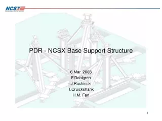
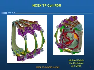
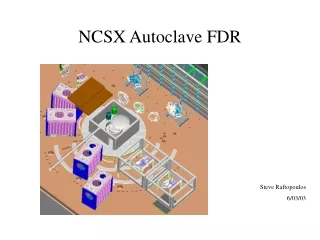
FDR - NCSX Central Solenoid Support Structure Fred Dahlgren Joe Rushinski 6 Sept 2006
FDR - Central Solenoid Support Structure - 9/6/06 Charge: Does the coil structure provide adequate support for the PF1a coils with sufficient margins of safety? Have the interfaces with other sub-systems been defined and are they compatible? Are the drawings and supporting documents complete and ready for sign-off? Has the analysis been documented and checked? Are the cost, procurement and assembly schedule consistent with the program schedule and budget?
FDR - Central Solenoid Support Structure - 9/6/06 Design Description: •The structure consists of solution annealed 304L stainless weldments fabricated mainly from 1/4”, 3/8”, 1/2” and 3/4” thick plate (µ < 1.02). •The individual structural segments are 120 degrees with G-11CR insulating plates, bushings, and washers between the adjacent segments. •A mid-plane sub-assembly will space the top & bottom PF1A coils (re-claimed from NSTX), at ± 40 cm from the mid-plane. •The top and bottom sub-assemblies will have six 3/4” tie rods with nuts and belleville washers and will provide a 12,000 lb. axial pre-load clamping force on the two PF1A coils. The bellevilles’ will accommodate up to 0.015” of differential thermal contraction/expansion (~ 0.007” amount required). •Twelve radial support arms (6-top & 6-bottom) will attach the solenoid structure to the main coil structure. •All bolting materials (nuts, bolts, washers, etc.) will be 316 stainless.
FDR - Central Solenoid Support Structure - 9/6/06 Coil Dimensions: 12.8” I.D. 16.26” O.D. 21.08” axial length 48 turns Cu area: 0.52 sq.in. Hole dia.: 0.354” Leads: 12.6” & 16.9” Fabr. Details see: NSTX-SPEC-13-041 Coil Description: 48 turn double layer spiral wound, 0.787” square CDA107 drawn Cu conductor with 0.354 dia. coolant hole. Insulation: 0.026” thk. CTD112P w/0.0065” Kapton-1/2-lapped (0.052” turn to turn) & 0.054” thk. ground wrap. PF1a Coil Modification: Water fittings & tubes must be re-worked & re-insulated
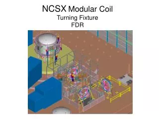
FDR - Central Solenoid Support Structure - 9/6/06 PF1a Coil/Structure Assembly - Pre-assembled
FDR - Central Solenoid Support Structure - 9/6/06 Assembly will have ~55” clearance for lift
Materials: 304L solution annealed plates ER316LN weld filler 316L nuts, bolts, washers, & rods G10/11CR insulating plates @ 120 deg. G10/11CR washers & bushings Copper tubing Brass Swagelok (B-600 series) tube fittings Interfaces: Cryogen cooling lines connect to top & bottom LN2 feed/return lines. Pressure & flow requirements defined, connecting lines (with insulating breaks) to cryogen supply & return plenums are needed. Four thermocouples are required to monitor coil inlet/outlet. Bus pads at the top & bottom locations are defined. Bus connection to power supply are needed. Bus interface defined, scenario A.1.3.4 defines the current & voltage requirements. Top & bottom mounting pads bolt to same threaded holes to be used for permanent solenoid supports. Loading @ support interface defined.
FDR - Central Solenoid Support Structure - 9/6/06 * * From Allegheny Ludlum Technical Data Blue Sheet
304L Properties* 2/3rd Yield allowable @80K = 46.6ksi * From Allegheny Ludlum Technical Data Blue Sheet
0.787 Ø 0.354 FDR - Central Solenoid Support Structure - 9/6/06 Cooling analysis: Plot of the PF1a exit temperature vs. time DP = 10 psi Qdot = 1.14 GPM AMPS = 19.3 kA ESW = 0.16 sec. Rep.Rate = 900 sec. Cooling Analysis Shows < 1 deg.K rise per pulse & no ratcheting
FDR - Central Solenoid Support Structure - 9/6/06 FEA Model of PF1A & Supporting Structure: • A 1/6th-Upper half Nastran linear FEA model was used. • PF1A coil modeled as discrete turns with insulating layers (CHEXA & CPENTA). • Structural components modeled with plate elements (CQUAD4 & CTRIA3). • Tie rods modeled with solid elements (CHEXA & CPENTA). • Bolts modeled with CBAR elements attaching plates & adjacent weldments. • EM loads on PF1A determined from dforce7b (Biot-Savart - U.C. code). • Symmetry boundary conditions were applied (toroidal, vertical and rotational). • Coil top & bottom surfaces not permitted to slide radially (rel. to supports). • Model Summary: Number of GRID Points = 21979 Number of CBAR Element = 57 Number of CHEXA Elements = 13232 Number of CPENTA Elements = 1696 Number of CQUAD4 Elements = 2287 Number of CTRIA3 Elements = 170 • Loading Conditions considered: Gravity, EM, Thermal, Seismic
FDR - Central Solenoid Support Structure - 9/6/06 3/4” Tie Rod / belleville washer, and bolted connection modeled
FDR - Central Solenoid Support Structure - 9/6/06 PF1A Coil Model: CPENTA & CHEXA isotropic Cu & Epoxy Glass
FDR - Central Solenoid Support Structure - 9/6/06 Loads considered: Gravity Loads with 1g & 2g vertical downward, B.C.: Symmetry & fixed at the upper bracket bolts (attached to the inner segmented ring castings which are assumed rigid). Horizontal seismic loading using static 0.15g acceleration per the NCSX/IBC2000 criteria (h~15ft, Fp=0.108 x 1.369 = 0.147 ~ 0.15g). B.C.: Symmetry & fixed @ upper bracket bolts. Thermally induced stress from cool down and temperature differentials using mean CTEs from R.T. to 77 oK. B.C.: Symmetry & fixed @ upper bracket bolts. (CTE-Cu from NIST data, CTE-304L from ITER data) Electro-magnetic loading for coil day-1 scenario A.1.3.2: Ipf1a = 19,299 A & 23,500 A (simulates M.C. loading) Ipf4 = 3,141 A Ipf6 = 241 A Ipl = -26,068 A & 0.0 A(Ipl = 0.0 was highest loading) B.C.: Symmetry & fixed @ upper bracket bolts.
FDR - Central Solenoid Support Structure - 9/6/06 Vertical Displacements for a 1-g gravity: Max = 0.0025”
FDR - Central Solenoid Support Structure - 9/6/06 Peak Tresca Stress: 3.44ksi Peak Tresca stress - 1-g loading: 3.44 ksi @ mtg. bolt holes
FDR - Central Solenoid Support Structure - 9/6/06 Vertical Displacements for (fault) 2g loading condition: -.005” max.
FDR - Central Solenoid Support Structure - 9/6/06 Tresca Z2 stress for a 2g loading condition (ie. if bottom supports loose or removed) Max Stress: 7ksi @ the mounting bolt holes
FDR - Central Solenoid Support Structure - 9/6/06 Peak Tresca Stress 2.0ksi Lateral 0.15g seismic displ. 0.002” at the middle of the tierod Peak Tresca stress 2 ksi @ the bolt hole Seismic (static) load 0.15g horizontal acceleration with top mtg. bracket fixed
FDR - Central Solenoid Support Structure - 9/6/06 Thermal Loading: Coil @ 80K & Structure @ R.T.(extreme case) Max Vertical displacement: -0.085” @ the top of the coil
FDR - Central Solenoid Support Structure - 9/6/06 Need to avoid extreme thermal differentials during cooldown Peak Tresca Stress 78.6 ksi >> yield stress & allowable
FDR - Central Solenoid Support Structure - 9/6/06 ∂y ~0.005” ∂y (tot.): -0.0115” A more realistic thermal loading assumes a temperature difference of 30 K and yields a relative vertical displacement of -0.012”. The differential rod & bellville to top plate shows about 0.005” - just over 50% of it’s linear range.
FDR - Central Solenoid Support Structure - 9/6/06 Peak Tresca: 15.6 ksi Peak Tresca stress for a 30 K temperature differential: 15.6 ksi
FDR - Central Solenoid Support Structure - 9/6/06 Tresca Peak Stress is 4.6 ksi in coil insulation for 30 oK temperature differential
FDR - Central Solenoid Support Structure - 9/6/06 Baseline EM Loads assumed the 0.5T 1st Plasma Scenario Coil EM Loading No Plasma: Fr = 4,369 lbs/in [5,660 lbs/in*] Fz = -3,722 lbs (total) [-6,355 lbs*] DFORCE7b result: Hoop Stress(avg.)=1.27ksi [1.84ksi*] Net Stress = 1.54ksi With Ipl = -26,068 amps Fr = 4,318 lbs/in Fz = -3,647 lbs (total) DFORCE7b result: Hoop Stress (avg.)=1.25ksi Net Stress = 1.53ksi *For Ipf1a = 23,500 Amps
FDR - Central Solenoid Support Structure - 9/6/06 EM Loading was calculated as J x B body forces at each coil turn. Genforce subroutine added to DFORCE7b to generate Nastran Force input. Equivalent discrete forces for the worst cases were applied at each of 6 interior element grid points. Centroidal currents (@ each turn) were assumed. The loading from the M.C. field was simulated by running a 23.5 kA PF1a current case, which duplicates the peak vertical loading from the M.C. radial fields.
FDR - Central Solenoid Support Structure - 9/6/06 Typical EM grid point load resultants @ 6 interior points in conductor
FDR - Central Solenoid Support Structure - 9/6/06 Peak Displ. 0.0005” Coil Displacements (SRSS) From 19.3kA EM Loads - No Axial Pre-load No Plasma -Maximum displacement was 0.0005” at the coil mid-plane
FDR - Central Solenoid Support Structure - 9/6/06 Peak Tresca: 1.83ksi Peak Tresca stress in the coil from 19.3kA EM loading only: 1.83 ksi
FDR - Central Solenoid Support Structure - 9/6/06 Peak Tresca Stress in supports 19.3kA EM + Thermal (cool-down): 14.0 ksi (with CONROD elements at bolt hole perimeter)
FDR - Central Solenoid Support Structure - 9/6/06 Peak Tresca Stress in supports 19.3kA EM + Thermal (cool-down): 2.51 ksi (with MPCs replacing CONROD elements at bolt hole perimeter)
FDR - Central Solenoid Support Structure - 9/6/06 Peak Tresca Stress in Cu 2.78 ksi Peak Tresca Stress in Coil for 23.5 kA EM-only loading, 2.78 ksi (Loading includes the effects of the M.C. peak fields)
FDR - Central Solenoid Support Structure - 9/6/06 Peak Tresca Stress in Support for 23.5 kA EM loading, 3.68 ksi
FDR - Central Solenoid Support Structure - 9/6/06 Peak Tresca Stress: 3.17 ksi Peak Cu Tresca Stress: ~2.9 ksi Peak Tresca Stress in coil insul. for 23.5 kA EM-Cold loading, 3.17 ksi, 2.9 ksi in Cu
FDR - Central Solenoid Support Structure - 9/6/06 Peak Displ. 0.167” (SRSS) Displacements for combined gravity, thermal, EM loading
FDR - Central Solenoid Support Structure - 9/6/06 Peak Tresca Stress = 3.16 ksi - insulation Average coil Tresca stress ~2-3ksi Tresca stress in coil from combined gravity, thermal, and EM loading
FDR - Central Solenoid Support Structure - 9/6/06 Peak Tresca Stress 2.68 ksi Peak Stress in supports from combined gravity, thermal, and EM load
FDR - Central Solenoid Support Structure - 9/6/06 Stress Analysis Summary *Allowable 304L @ 80 oK = 46.6 ksi (321 MPa) (2/3rd yield criteria) Allowable CDA107(10%CW) Cu @ 80 oK = 16 ksi (110.6 MPa) (2/3rd yield criteria) ** Allowable CTD112P-w/Kapton @ 80 oK = 8.86 ksi (61.3 Mpa 2/3rd ultimate criteria) -per ITER test data § Actual margins on max shear are double these values (C2 = 0.6, Sc= 0.0 - Eqn. From NCSX design criteria, 5.6 ksi no compr.) **Sy = 124 - 0.241xT +14.1xCW - 0.166xCW2 = 230.5MPa, 2 x sigma = 64 MPa, 230 - 64 = 166, 2/3 x 166 = 110.6 MPa (16 ksi) (From NIST Monograph 177 -Simon, Drexler, Reed)
FDR - Central Solenoid Support Structure - 9/6/06 Coil Testing Requirements: Electrical After re-configuring and re-insulation of coolant tubes, coils will require a hi-pot to ground at 2 kV (2 x Vop. +1000) and a megger at room temperature and 80 deg.K. Insulating breaks between field periods will be meggered @ 2kV Mechanical During cool-down for 80 deg.K electrical test, a flow measurement for a delta-P of 10psi will be required. Thermocouples on inlet and outlet tubes will be needed to provide a record of T vs. time for the cool-down.
FDR - Central Solenoid Support Structure - 9/6/06 Cost & schedule: •Build in-house preliminary est: ~75k$ •Will issue an RFQ for 304L & 316L by late Sept.’06 •Anticipate a 4-6mo. Delivery •A 316L material may delay things a month or two and may cost 30% more.
FDR - Central Solenoid Support Structure - 9/6/06 Conclusions: Charge: Does the coil structure provide adequate support for the PF1a coils with sufficient margins of safety? A: Stress margins on allowables for both coil and support exceed project & code requirements. Have the interfaces with other sub-systems been defined and are they compatible? A: Interfaces to machine structure, cryo-system, and electrical power defined & compatible. Are the drawings and supporting documents complete and ready for sign-off? A: Drawings & BOM are complete and ready for checking/sign-off. Has the analysis been documented and checked? A: The stress & thermal analysis have been documented & are being checked. Are the cost, procurement and assembly schedule consistent with the program schedule and budget? A: Cost & schedule are consistent with project schedule and, pending responses from RFQ, should fall within the current project budget.
FDR - Central Solenoid Support Structure - 9/6/06 per A.Brooks 9/1/06
FDR - Central Solenoid Support Structure - 9/6/06 per A.Brooks 9/1/06
FDR - Central Solenoid Support Structure - 9/6/06 Fatigue analysis: 304L Peak Tresca Stress: 15.6 ksi (EM + 1g + 30 oK delta) Operating stress below the s/2 @ 130,000 cycles 15 20x life The 2/20 project criteria for fatigue is satisfied although the anticipated usage of the PF1a coils and supports is significantly less than the 130,000 cycles.
FDR - Central Solenoid Support Structure - 9/6/06 Shear Strength CTD112P (w/Kapton) 13.3 ksi @77 deg.K
FDR - Central Solenoid Support Structure - 9/6/06 ITER shear-compression tests Max Shear: 6.78 ksi for 15 degree angle(12ksi compr.) @ 77 deg. K 6.7 ksi 40 MPa, 5.8 ksi-static & fatigue
FDR - Central Solenoid Support Structure - 9/6/06 Inner radial stop will maintain central alignment of PF1a coils