Download
1 / 21
210 likes | 215 Views
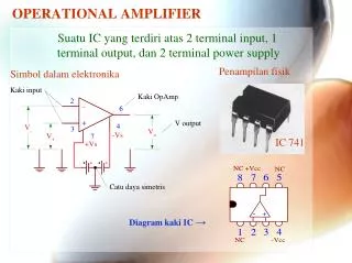
The basic Op-amp construction is of a 3-terminal device, with 2-inputs and 1-output, (excluding power connections). u2022 An Operational Amplifier operates from either a dual positive ( V ) and an corresponding negative ( -V ) supply, or they can operate from a single DC supply voltage.

E N D
Electronics – 1 OP-AMP
ABOUT ME ABU BAKAR NATIONALITY : PAKISTAN CITY : SIALKOT, PUNJAB MARITAL STATUS : SINGLE Tel: (+92) 322 7967172 E-Mail:abubakarmehmood786@yahoo.com CONTACT INFO PERSONAL PROFILE THE CREATOR ACADEMY thecreatorsacademyofficial The Creators Academy thecreatorsacademyofficial BS(HONS) PHYSICS UNIVERSITY OF SIALKOT UCQxAo-GBHUI2l9_LBYicsRw FOUNDER EDUCATION ORIGIN LAB, VIRTUAL LAB, ENDNOTE SOFTWARE, EMATHHELP SOFTWARE , MICROSOFT OFFICE, ADBOBE (PHOTOSHOP & ILUUSTRATOR), ARDUINO SOFTWARE, AMAZON VITUAL ASSISTAN, VIDEO EDITTING, SOCIAL MEDIA ACCOUNT MANAGEMENT URDU, PUNJABI, ENGLISH, ARABIC ABUBAKAR692909 @abubakar786786 Abubakar Bhutta @_abubakar786 ABU BAKAR SOCIAL MEDIA SKILLS & LANGUAGE
Presentation Outline • Introduction ( History + What is an Op-Amp?) • Characteristics of Ideal and Real Op-Amps • Applications • Advantages/disadvantages
What is an Op-Amp? • An Operational Amplifier (known as an “Op-Amp”) is an integrated circuit that sets an output voltage based on the input voltages provided. • The term “operational amplifier” denotes a special type of amplifier that, by proper selection of its external components, could be configured for a variety of operations. • In a circuit, it is used to perform an operation and an amplification where the operation may be add, subtract, filter, integrate, differentiate, etc. • Op-Amps are composed of transistors, resistors, capacitors, and diodes.
Brief History • 1941: Karl Swartzel of Bell Labs developed the first Op-Amp. • Used 3 vacuum tubes, only one input (inverting), and operated on + 350 V to achieve 90 dB gain. • 1947: Loebe Julie developed the Op-Amp as it is known today, with two inputs – inverting and non-inverting. • The differential input made a whole range of new functionality possible. • 1953: First commercially available Op-Amp. • George A. Philbrick Researches (GAP-R). GAP-R pioneered the first reasonable-cost, mass-produced operational amplifier • 1961: Advent of solid-state, discrete Op-Amps. • Made possible by the invention of the silicon transistor, which led to the concept of Integrated Circuits (IC) • Reduced power input to ±15V to ±10V • 1962: Op-Amp in a potted module. • Packaging in small black boxes allowed for integration with a circuit
Brief History • 1963: First monolithic IC Op-Amp, the μA702, designed by Bob Widlar at Fairchild Semiconductor. • Monolithic ICs consist of a single chip • 1968: Release of the μA741 • The μA741 became the canonical Op-Amp, from which many modern op-amps base their pinout from, and is still in production today. Note : The latest generation op amps cover the frequency spectrum from 5-kHz GBW to beyond 1-GHz GBW. The supply voltage ranges from guaranteed operation at 0.9 V to absolute maximum voltage ratings of 1000 V. The input current and input offset voltage has fallen so low that customers have problems verifying the specifications during incoming inspection. The op amp has truly become the universal analog IC because it performs all analog tasks.
Fig.. Ckt symbol for general purpose op-amp Figure showsthe symbol of op-amp & the power supply connections to make it work. The input terminal identified by the ‘-’ and “+” symbols are designated inverting & non- inverting. Their voltage w.r.t ground are denoted as VN & VP and output voltage as VO. Op- amp do not have a zero volt ground terminal Ground reference is established externally by the power supplycommon.
Op-amp pin diagram There are 8 pins in a common Op-Amp, like the 741 which is used in many instructionalcourses. Pin 1: Offsetnull Pin2: Inverting inputterminal Pin 3: Non-invertinginput terminal Pin 4: –VCC (negative voltage supply) Pin 5: Offsetnull Pin 6: Outputvoltage Pin 7: +VCC (positivevoltage supply) Pin 8: NoConnection Figure : Pin connection,LM741.
Important termsand equation VN a = gain ofamplifiers. Vd= difference between the voltage. V0= gain ofvoltage. The equation: V0 = a (VP -VN) Electrical parameter: V0 Vd Vp Input bias current(Ib): average of current that flows into the inverting and non-inverting input terminal ofop-amp. I/p and o/p impedance: It is the resistance offered by the inputs and the output terminals to varying voltages. The quantity is expressed inOhms. Open Loop Gain: It is the overall voltage gain or theamplification. Input offset voltage : It is a voltage that must be applied between the two terminal ofan op-amp to null theo/p. Input offset current (Ii): The algebraic different between the current in to the inverting and Non-invertingterminal.
Presentation Outline • Introduction (Op-Amp + History) • Characteristics of Ideal and Real Op-Amps • Applications • Advantages/disadvantages
Basic Op-Amp (Open-Loop) • : positive power supply • : negative power supply • : non-inverting input terminal • : inverting input terminal • : output terminal • ,, are all referenced to ground
Ideal Op-Amp • Temperature-independent. • The maximum output voltage value is the supply voltage (saturation): • What this means: • Current flow into the op-amp from either input terminal is zero. • Differential voltage between the two input terminals is zero.
Real Op-Amp • Operating temperature range: • Commercial: • Industrial: • Military:
CHARACTERISTICS OF IDEAL OP-AMP • Infinite input impedance(about2Mohm) • Low output impedance(about 200ohm) • Very large voltage gain at lowfrequency • Thus, small changes in voltages can be amplified byusing anop-amp • Infinite bandwidth(all frequencies are amplified by same factor • Infinite Common-mode rejectionratio • Infinite Power supply rejectionratio. • Finite open-loop gain that causes gainerror • Finite inputimpedance • Non zero outputimpedance • Finite CMRR • Common-mode inputresistance • Finite bandwidth • Finite power supply rejectionratio.
Presentation Outline • Introduction (Op-Amp + History) • Characteristics of Ideal and Real Op-Amps • Applications • Advantages/disadvantages
APPLICATIONS • A to D Converters • Powersource • Zero Crossing Detector(ZCD)
1.A to DConverters Figure 1 – Digital processing system with an ADC at the input and a DAC at theoutput
2.Op-AmpasaCurrentSource A current source can be made from an inverting amplifier as shown in figure. The current in the load resistor, R0 must be equal to the current in R1.Thecurrent is then obtained by dividing the input voltage byR1.
3.Zero crossing detectorapplications ZCD circuit can be used to check whether the op-amp is in good condition. Zero crossing detectors can be used as frequency counters and for switching purposes in power electronics circuits. ZCD is a basic op ampcircuit.
ADVANTAGES OF ANOP-AM:- • OPAM IS AN UNIVERSAL AMPLIFIER. • VOLTAGE COMPARATORS. • PRECISION RECTIFIERS. • ANOLOGUE TO DIGITAL CONVERTERS. • DIGITAL TO ANALOGUE CONVERTERS. • FILTERS • DIFFRENTIATORS AND INTEGRATORS. • VOLTAGE AND CURRENT REGULATOR. • ANALOGUE TO COMPUTERS.
DISADVANTAGES OF ANOPAM:- • 1. MOSTOPAMARE DESIGNED TO FORLOWER POWEROPERATION. • 2.FOR HIGH OUTPUT IS DESIRED THEN THE OPAMSPECIFICALLYDESIGNEDFOR THAT PURPOSE MUSTBESEEN. • 3.MOST COMMERCIAL OPAM SHUTS OFF WHEN THE LOAD RESISTANCE IS BELOW A SPECIFIC LEVEL.