Download
1 / 31
310 likes | 322 Views
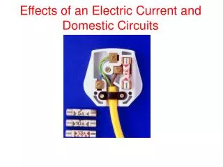
EMT 114/3 INTRODUCTION TO ELECTRIC CIRCUITS. Chapter 2 Resistive Circuit. School of Microelectronic Engineering, Universiti Malaysia Perlis. Intro to Resistive Circuit. A resistive circuit is a circuit containing only resistors and ideal current and voltage sources.

E N D
EMT 114/3INTRODUCTION TO ELECTRICCIRCUITS Chapter 2 Resistive Circuit School of Microelectronic Engineering, Universiti Malaysia Perlis
Intro to Resistive Circuit • A resistive circuit is a circuit containing only resistors and ideal current and voltage sources. • Analysis of resistive circuits is less complicated than analysis of circuits containing capacitors and inductors. • If the sources are constant (DC) sources, the result is a DC circuit. School of Microelectronic Engineering, Universiti Malaysia Perlis
Outline • Series and Parallel Resistor • Voltage Divider • Current Divider • Voltage and Current Measurements • Wheatstone Bridge • Delta-Wye Equivalent Circuits School of Microelectronic Engineering, Universiti Malaysia Perlis
1. Series and Parallel Resistor A) Series Resistor Two or more elements are in series if they exclusively share a single node and consequently carry the same current. B) Parallel Resistor Two or more elements are in parallel if they are connected to the same two nodes and consequently have the same voltage across them School of Microelectronic Engineering, Universiti Malaysia Perlis
Series Resistors & Connection Resistance equivalent Req = R1 + R2 + ……….+ RN School of Microelectronic Engineering, Universiti Malaysia Perlis
Characteristics of series Circuits Resistance The equivalent resistance of any number of resistors connected in a series is the sum of the individual resistances. Req= R1+R2+……+RN = Current The amount of current is the same through the circuit. Voltage Voltage (VT) in series is the total voltage for each elements School of Microelectronic Engineering, Universiti Malaysia Perlis
Parallel Resistors &Connection School of Microelectronic Engineering, Universiti Malaysia Perlis
Characteristics of parallel Circuits Resistance The equivalent resistance is reciprocal of total resistance Current Current in parallel circuits is the total current for each of the circuits elements Voltage Voltage (VT) for parallel circuits is the same for all circuits elements School of Microelectronic Engineering, Universiti Malaysia Perlis
Example1: Find the current through the 5 volt source by simplifying the resistors to a single equivalent resistance. 10 || 20 and 30 || 40. And then both equivalent resistors are connected in a series. I = V/R = 5 V / 23.81ohms = 210 mA School of Microelectronic Engineering, Universiti Malaysia Perlis
Example2: Find the equivalent resistance of the circuit network shown above. Req = 7 + 5 = 12 ohms School of Microelectronic Engineering, Universiti Malaysia Perlis
Example3: Find the equivalent resistance of the circuit network shown above. Try thinking of a current source pumping current into the 3k ohm resistor. All the current will go through the short on the left and NONE of it will go through the 2k and the 4k. It will then go through the 5k ohm to get back to the source. That is to say, the 2k and the 4k are shorted out by the wire. Req = 3k + 0 + 5k = 8k ohms School of Microelectronic Engineering, Universiti Malaysia Perlis
2. Voltage Divider By Applying Ohms Law; V=IR So; V1 = IR1 V2 = IR2 V = V1+ V2 = I(R1+R2) I= V/ (R1+R2) School of Microelectronic Engineering, Universiti Malaysia Perlis
Cont.. In general, voltage drop across any resistor, or combination of resistors, in a series circuit is equal to the ratio of that resistance value to the total resistance, multiplied by the source voltage. Voltage drop across R2, V2=IR2 V2=(V/ R1+R2) x R2 = School of Microelectronic Engineering, Universiti Malaysia Perlis
Example4: Find the voltage drop across the resistors. School of Microelectronic Engineering, Universiti Malaysia Perlis
3. Current Divider By Applying Ohms Law; V = I1R1 = I2R2, = IReq I1= V/R1 and I2= V/R1 ----equation 1 Total current flow; V= IReq ----------equation 2 Where Req = (R1R2/R1+R2) School of Microelectronic Engineering, Universiti Malaysia Perlis
Cont.. In general, the current in any branch is equal to the ratio of opposite branch resistance to the total resistance value, multiplied by the total current in the circuit • (2) (1) : given, School of Microelectronic Engineering, Universiti Malaysia Perlis
Example: Determine the branch currents through individual resistors I1, I2, 13, == 6mA,2mA,3mA School of Microelectronic Engineering, Universiti Malaysia Perlis
4.Voltage and Current Measurements Instrumentation: Ammeter • Is an instrument designed to measure current • It is placed in series with the circuit element whose current is being measured • An ideal ammeter has an equivalent resistance of 0Ω and functions as short circuit in series with the element whose current is being measured School of Microelectronic Engineering, Universiti Malaysia Perlis
Cont.. Voltmeter • Is an instrument designed to measure potentialdifferent (voltage) between two point in the circuit. • It is placed in parallel with the element whose voltage is being measured • An ideal voltmeter has infinite equivalent resistance and thus functions as an open circuit in parallel with the element whose voltage is being measured School of Microelectronic Engineering, Universiti Malaysia Perlis
Circuit configuration with Ammeter and Voltmeter connection School of Microelectronic Engineering, Universiti Malaysia Perlis
5. Wheatstone Bridge • Wheatstone bridge is a circuit used to precisely measure resistance in the range from 1Ω to 1MΩ with ±0.01% accuracy • R1 and R2 are resistors with known values • R3 is a variable resistor (typically 1 to 1.1kΩ) • Rx is the resistor whose value is to be measured School of Microelectronic Engineering, Universiti Malaysia Perlis
Problem Solving; Then; Finding the Rx value: School of Microelectronic Engineering, Universiti Malaysia Perlis
6. Delta-Wye Equivalent Circuits If the galvanometer in the Wheatstone bridge is replaced with equivalent resistance Rm School of Microelectronic Engineering, Universiti Malaysia Perlis
Delta (Δ) and Pi (π) The resistor R1,R2 and Rm (or R3,Rm and Rx) are referred as a Δ interconnection. It is also is referred as a π interconnection because the Δ a can be shaped into a π without disturbing the electrical equivalence of the two configurations. School of Microelectronic Engineering, Universiti Malaysia Perlis
Wye(Y) and Tee(T) The resistor R1,R3 and Rm (or R2,Rm and Rx) are referred as a Wye (Y) interconnection because it can be look like letter Y. The Y configuration also referred as Tee (T) interconnection. School of Microelectronic Engineering, Universiti Malaysia Perlis
Problem SolvingDelta(Δ) to Wye(Y) Transformation In order for delta interconnection to be equivalent to the Wye interconnection, the resistance between corresponding terminal parts must be the same School of Microelectronic Engineering, Universiti Malaysia Perlis
Δ-Y and Y-Δ Conversion Formula: School of Microelectronic Engineering, Universiti Malaysia Perlis
Exercise 1 Find the equivalent resistance at terminals a-b for electrical network below; School of Microelectronic Engineering, Universiti Malaysia Perlis
Exercise 2 By a given voltage, Vs, calculate the current through the R1 and R2. School of Microelectronic Engineering, Universiti Malaysia Perlis
Exercise 3 Calculate the current and power supplied by the 40V sources in the circuit shown below; School of Microelectronic Engineering, Universiti Malaysia Perlis
Ilmu Keikhlasan Kecemerlangan School of Microelectronic Engineering, Universiti Malaysia Perlis