Download
1 / 38
400 likes | 628 Views
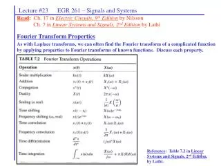
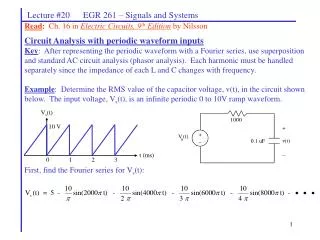
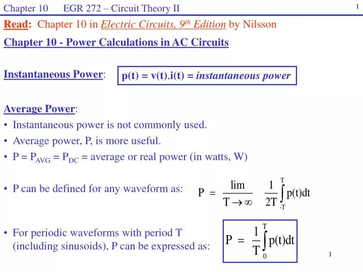
Chapter 10 EGR 272 – Circuit Theory II. 1. Read : Chapter 10 in Electric Circuits, 9 th Edition by Nilsson. Chapter 10 - Power Calculations in AC Circuits Instantaneous Power :. p(t) = v(t) i (t) = instantaneous power. Average Power :

E N D
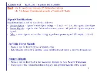
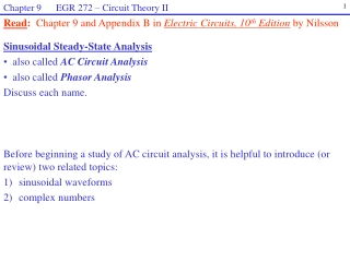
Chapter 10 EGR 272 – Circuit Theory II 1 Read: Chapter 10 in Electric Circuits, 9thEdition by Nilsson Chapter 10 - Power Calculations in AC Circuits Instantaneous Power: p(t) = v(t)i(t) = instantaneous power • Average Power: • Instantaneous power is not commonly used. • Average power, P, is more useful. • P = PAVG = PDC = average or real power (in watts, W) • P can be defined for any waveform as: • For periodic waveforms with period T (including sinusoids), P can be expressed as:
Chapter 10 EGR 272 – Circuit Theory II 2 Average power can be calculated: 1) by inspection (for simple cases) 2) by integration (for more complex cases) Example: Find the average power absorbed to the resistor below.
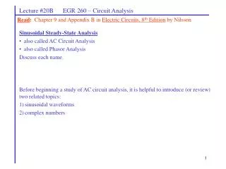
Chapter 10 EGR 272 – Circuit Theory II 3 v(t) [V] i(t) + 20 v(t) 10 t [s] _ 0 0 2 4 6 8 10 12 Example: Find the average power absorbed to the resistor below.
Chapter 10 EGR 272 – Circuit Theory II 4 RMS Voltage and Current VRMS = root-mean-square voltage (also sometimes called Veff = effective voltage) VRMS = the square root of the average value of the function squared Note how the name RMS essentially gives the definition.
Chapter 10 EGR 272 – Circuit Theory II 5 Calculating average power for a resistive load using RMS values A key reason that RMS values are used commonly in AC circuits is that they are used in power calculations that are very similar to those used in DC circuits. Recall that power in DC circuits can be calculated using: Similarly, instantaneous power to a resistor can be calculated using Show that power can be also be calculated using RMS values as follows: Development:
Chapter 10 EGR 272 – Circuit Theory II 6 RMS values can be calculated: 1) by inspection (for simple cases) 2) by integration (for more complex cases) Example: Find IRMS for the waveform below and use IRMS to calculate the average power absorbed to the resistor. Recall that P was calculated earlier using instantaneous power.
Chapter 10 EGR 272 – Circuit Theory II 7 v(t) [V] i(t) + 20 v(t) 10 t [s] _ 0 0 2 4 6 8 10 12 Example: Find VRMS for the waveform below and use VRMS to calculate the average power absorbed to the resistor. Recall that P was calculated earlier using instantaneous power.
Chapter 10 EGR 272 – Circuit Theory II 8 RMS value of sinusoidal voltages and currents Using the definition of RMS voltage and current, it can be shown that for a sinusoidal voltage v(t) = Vpcos(wt) and a sinusoidal current i(t) = Ipcos(wt) that: Development: Derive the expression for VRMS above. Example: Find the power absorbed by a 10 resistor with v(t) = 20cos(377t) V.
Chapter 10 EGR 272 – Circuit Theory II 9 Superposition of Power Recall that, in general, superposition applies to voltage and current, but not to power. Applying superposition to find the current i: i = i1 + i2 or i = current due to V1 + current due to V2 Show that this leads to: P P1 + P2 Development:
Chapter 10 EGR 272 – Circuit Theory II 10 Power to a Complex Load If v(t) = Vmcos(wt) then i(t) = Imcos(wt - ) Useful identities: cos(wt - ) = cos()cos(wt) + sin()sin(wt) cos2 (wt) = ½ + ½ cos(2wt) sin(wt)cos(wt) = ½ sin(2wt) Show that: Development:
Chapter 10 EGR 272 – Circuit Theory II 11 Key definitions: Recall that real or average power, P, was just defined as: Other important terms are apparent power and power factor, as defined below: Apparent power = (VRMS)(IRMS) measured in volt-amperes, VA • Since cos is an even function (i.e., cos() = cos(-)), calculating cos() does not reveal the sign of the angle, so the terms leading and lagging are used with power factor. • The power factor is leading if < 0, (i.e., I leads V or the load is capacitive). • The power factor is lagging if > 0, (i.e., I lags V or the load is inductive).
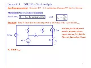
Chapter 10 EGR 272 – Circuit Theory II 12 + Z 10V RMS _ Examples: Determine P and the p.f. for each case below:
Chapter 10 EGR 272 – Circuit Theory II 13 Complex Power: The use of phasors with RMS values is very convenient for power calculations. Define
Chapter 10 EGR 272 – Circuit Theory II 14 Since Show that where Development:
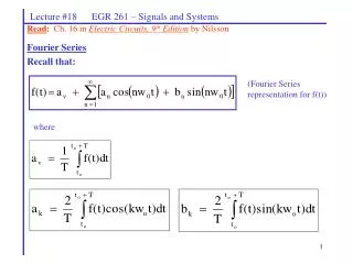
Chapter 10 EGR 272 – Circuit Theory II 15 Im S Q |S| Re P |S| Q P Complex Power Diagram A complex power diagram is sometimes used to illustrate the relationship between P, Q, |S|, and S. or Example: If VRMS = 1000 V and IRMS = 5 -30 A, find P, Q, |S|, and S and illustrate them on a complex power diagram. Also find the power factor.
Chapter 10 EGR 272 – Circuit Theory II 16 Other useful relationships Substitute VRMS = ZIRMSand Z = R + jX into S = VRMSIRMS*to show that: Development:
Chapter 10 EGR 272 – Circuit Theory II 17 Two approaches for performing power calculations: 1. 2. Find the voltage or current for each component (magnitude only). Then calculate P or Q for each component and add the results for total P and Q.
Chapter 10 EGR 272 – Circuit Theory II 18 10 15 + 100V RMS 26.5 mH 132.6 uF 60 Hz _ Example: A) By first finding the total circuit impedance
Chapter 10 EGR 272 – Circuit Theory II 19 10 15 + 100V RMS 26.5 mH 132.6 uF 60 Hz _ Example: (continued) B) By finding P or Q for each component (use mesh equations first to find the currents for each component).
Chapter 10 EGR 272 – Circuit Theory II 20 Power Factor Correction Power companies charge their customers based on the real power (P) used. If the customer has a significant amount of reactive power (or a low power factor) this has no effect on P, but results in higher current levels. Power companies “encourage” their large customers to “correct” their power factor. If their power factor drops too low (perhaps less than 0.9), the power company may charge higher rates. Large companies often have lagging power factors due to large amounts of machinery (inductive loads) and they can correct their power factor by adding in large parallel capacitors (or use synchronous motors). This generates negative reactive power that cancels the positive reactive power due to the inductive loads resulting in a power factor which is near or close to unity. The corrected power factor results in lower current levels and thus lower line losses (I2 R) as the power company delivers the power to the customer. Use user also benefits from lower current levels since maximum current ratings on wire and equipment can be reduced.
Chapter 10 EGR 272 – Circuit Theory II 21 Illustration - Power Factor Correction I1 I2 I1 + + IC C Circuit Circuit _ _ Original Circuit New Circuit (Note that |I2| < |I1| ) Im Im Im Q Re Re Re P P QC = -Q Original Circuit + Added Capacitor = New Circuit S = P + jQ S = P + jQ S = P + jQ - jQ = P
Chapter 10 EGR 272 – Circuit Theory II 22 10 15 + 100V RMS 26.5 mH 132.6 uF 60 Hz _ Example: Add a capacitor in parallel with the source in order to: A) correct the power factor to unity Also calculate the total source current and compare it to the original current. Note that this is the same circuit analyzed previously.
Chapter 10 EGR 272 – Circuit Theory II 23 Example: (continued) Add a capacitor in parallel with the source in order to: B) correct the power factor to 0.95, lagging Also calculate the total source current and compare it to the original current. Summary: (Parts A and B)
Chapter 10 EGR 272 – Circuit Theory II 24 + Subsystem 1: |S| = 2000 VA p.f. = 0.8, lagging Subsystem 2: P = 2000 W p.f. = 0.9, leading Subsystem 3: |S| = 2000 VA Q = 1500 VAR _ Power Factor in Systems Just as total power can be determined by adding the power dissipated by each component, so can the total power for a system be determined by adding the power dissipated by each subsystem. Example: Find the power factor of the entire system below that is comprised of three subsystems as shown below.
Chapter 10 EGR 272 – Circuit Theory II 25 Transformers: Our earlier study of inductors introduced the idea that current through a set of windings creates a magnetic field and magnetic flux, , flows through the core. If then flows through a second set of windings another magnetic field is created and a secondary voltage is induced across these windings. This arrangement of two windings on a common core is called a transformer (illustrated below).
Chapter 10 EGR 272 – Circuit Theory II 26 Recall that = flux linkage N = number of turns = magnetic flux (in Webers, Wb) and = N = Li , where L = inductance in Henries, H Also So Since the same magnetic flux, , flows through the windings it is also true that the rate of change of magnetic flux, d/dt is the same, so where a = turns ratio
Chapter 10 EGR 272 – Circuit Theory II 27 Key transformer relationships We just saw that Similarly where a = turns ratio so
Chapter 10 EGR 272 – Circuit Theory II 28 Transformer symbols General Transformer Iron-core Transformer
Chapter 10 EGR 272 – Circuit Theory II 29 Examples of transformers (reference: www.allelectronics.com) Primary: 120V Secondary: 40VCT, 0.25A Primary: 120V Secondary: 28V, 1.5A Primary: 110V Secondary: 15V, 0.4A Utility pole transformer
Chapter 10 EGR 272 – Circuit Theory II 30 Examples of transformers (reference: www.allelectronics.com) PC Mount Transformer Primary: 120V Secondary: 16VCT, 0.8A or 8V, 1.6A Toroidal Transformer Primary: 120V Secondary: 8.5V and 9.4V Variac (Variable Transformer) Input: 110V Output: 0 to 130V Up/Down Transformer (110V to 220V) or (220V to 110V)
Chapter 10 EGR 272 – Circuit Theory II 31 a : 1 N1:N2 i1 i2 + + V1 V2 _ _ Dot Convention The direction of the windings in the secondary with respect to the direction of the windings in the primary determines the polarity of the secondary voltage. However, rather than showing the direction of the windings, dots are often placed at one end of each winding. Then the following convention applies: Dot convention: “A positive voltage at one dotted terminal will produce a positive voltage at the other dotted terminal.” • Note that the relationships • Imply that: • the positive terminals of V1 and V2 are at the dotted terminals • I1 enters the dotted terminal and I2 leaves the dotted terminal • These voltage polarities and • current directions are indicated • to the right.
Chapter 10 EGR 272 – Circuit Theory II 32 • Four Common Transformer Uses • Change voltage levels • Change current levels • Change impedance levels (impedance matching) • Isolation (e.g., to isolate the secondary load from the ground in the primary) Examples: Show simple examples of the four transformer uses listed above.
Chapter 10 EGR 272 – Circuit Theory II 33 1:2 20 mF 5 + 2 + V1 5 cos(10t) 20 mH _ _ i2 Example: Determine the V1 and i2 in the circuit below. Find these values by: A) Using KVL equations around each loop
Chapter 10 EGR 272 – Circuit Theory II 34 1:2 20 mF 5 + 2 + V1 5 cos(10t) 20 mH _ _ i2 Example: Determine the V1 and i2 in the circuit below. Find these values by: B) Reflecting the impedance of the secondary to the primary.
Chapter 10 EGR 272 – Circuit Theory II 35 1:2 3:1 1:2 a 10 10 10 Zab 10 b Example: Determine the value of Zab below.
Chapter 10 EGR 272 – Circuit Theory II 36 Example: Recall the example presented in EGR 271 where a transformer was used to insure that maximum power was delivered to a 4 ohm speaker from the output of an amplifier with an output resistance of 100 ohms. Illustrate and discuss.
Chapter 10 EGR 272 – Circuit Theory II 37 a:1 62.5 pF 80 W 320 + L 100cos(105t) V _ Example: Determine the inductance, L, and the turns ratio, a, required to achieve maximum power transfer to the secondary load.
Chapter 10 EGR 272 – Circuit Theory II 38 Transformer Models: Transformers considered in this course have been considered to be ideal. Although transformer behavior is often close to ideal, there are cases where non-ideal behavior might be examined. The figures to the left (reference: Electric Power & Machinery by Matsch) show models of a transformer used to approximate non-ideal behavior. The resistances, R1 and R2, represent the resistance of the windings and the inductive reactances, Xl1 and Xl2 represent leakage magnetic flux.