Download
1 / 39
420 likes | 1.49k Views
Hershey Lodge Preconference Symposium 17 March 2008. Structural Concrete Innovations: A Focus on Blast Resistance. Blast Overview. Blast can effect structure in multiple way Air blast Drag Ground shock Primary and secondary fragmentation Fire. Blast Loading.

E N D
Hershey Lodge Preconference Symposium 17 March 2008 Structural Concrete Innovations: A Focus on Blast Resistance
Blast Overview • Blast can effect structure in multiple way • Air blast • Drag • Ground shock • Primary and secondary fragmentation • Fire
Blast Loading • Air blast design can be governed by max pressure, impulse, or combination • Function of size of explosive, standoff distance, and structure
Air Blast Loads • Properties of the air blast load a function of the: • Size and shape of explosive • Distance to explosive • Orientation of specimen • Type of blast • Free air burst • Ground burst • Contained burst
Scaled Distance • Convert explosive to equivalent weight of TNT • Determine scaled distance using Z = D / W^(1/3) where Z = scaled distance W= equivalent TNT weight D = distance between specimen and explosive • Use figures in references (TM5-1300): “Structures to Resist the Effects of Accidental Explosions” • determine the expected peak pressure and impulse for determined scaled distance
Types of Cross Sections • TM5-1300: 3 types of cross sections • Type I: • Concrete is sufficient to resist compressive component of moment • Cover remains undamaged • Type II: • Concrete is no longer effective at resisting moment • Equal top and bottom reinforcement • Cover remains in tact • Single leg stirrups used to resist shear • Type III: • Equal top and bottom reinforcement • Cover disengages • Lacing used to resist shear
Motivation for Innovation in Blast Resistant Concrete • Increased demand for impact and blast-resistant building materials • Need for practical, constructible options • Need for reduction in secondary fragmentation
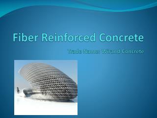
Innovation • Long (3”) fibers • Increased bond with concrete matrix • Length provides crack bridging, spalling resistance, increased ductility, energy absorption (through long-fiber pull-out) • Coated “tape” • Mix retains workability (no balling, etc) • Can be used with aggregate • Potentially economical • Carbon fiber yarn is waste product from the aerospace industry • No special mixers required • Lightweight “additive” reinforcement • Precast or cast-in-place • Molds to any shape
Experimental Program • Mix design development • Workability • Static flexural strength • Small and large scale • Ductility • Impact testing • Small beams • Panels • Blast Testing • Finite Element Modeling
Experimental Program • Mix design development • 1.5% to 2.5% fiber content (by volume) • Various admixture combinations • Pozzolans (interground SF + GGBFS)
Preliminary Testing • Mixture Design • Avoid balling • Increase workability • Increase fines and cement in mixture • Preliminary Static Tests • 6” X 6” X 18” beams loaded at third points • Flexural Strength = 2112 psi
Slab Strips • 4” X 12” X 10’ slab strips loaded at midspan • Specimens: • 2 control specimens with reinforcing mesh • 2 fiber reinforced concrete specimens • 2 fiber reinforced concrete specimens with mesh • Used to obtain load vs. deflection plot • Useful for obtaining toughness
Impact Test Setup • 15 ft maximum drop height • 50# weight • Panels 2’x2’x2”
Impact Testing: Panels Drop Height at failure
Impact Testing: Panels Drop Height at first cracking (top side)
Impact Testing: Panels(No Steel Reinforcement) • Fiber addition controlled spalling • Failure in fiber specimens along weak plane due to fiber orientation Fiber panel Plain panel
Impact Testing: Panels(Steel Reinforcement) • Fiber panel with steel reinforcement did not fail after repeated blows at top drop height Plain panel Fiber panel
Blast Testing • 6’ x 6’ x 6.5” • Heavily reinforced (as per TM5-1300) • resist shear failure at supports • evaluate comparison of materials under full blast design • Identical reinforcement in all specimens • Clear cover ¾” to ties
Test Setup • Slabs were simply supported on all four sides • Restraint provided along two sides to prevent rebound
Test Setup • TNT suspended at desired height • Pressure gages record reflected pressure and incident pressure
Hit 1: 75# at 6’ (scaled range 1.4) Extensive cracking, some spalling A few hairline cracks SafeTcrete Standard Concrete
Hit 2: 75# at 3.2’ (scaled range 0.76) SafeTcrete Standard Concrete
Hit 2: 75# at 3.2’ (scaled range 0.76) Concrete rubble within steel cage Some concrete loss due to pop out where reinforcement buckled (3/4” cover) Standard Concrete SafeTcrete
Hit 2: 75# at 3.2’ (scaled range 0.76) Standard Concrete SafeTcrete
Summary of Impact & Blast Testing • Much improved workability and dispersion of coated tape fibers • Increased ductility over plain concrete and further improved combined with standard reinforcement • Significantly increased flexural strength under both static and impact loads • Complete control of spalling in panels under impact load • Excellent performance in blast testing
Potential • Low cost fiber alternative • Applications requiring impact and blast resistance • Protective cladding panels • Structural components: columns, walls • Barriers • Bridge piers • May be used as a replacement for, or in combination with standard reinforcement depending on application
Material Properties • Stress-strain curves for material in both compression and tension needed for modeling • Compression: standard 6” diameter cylinders • Tension: dogbone specimens will be utilized • Varied load rates and fiber orientation
Tensile Properties • New test method for tension in fiber concrete • Difficulties with direct tension • Size-effect with long-fibers • Dogbone specimens 32” high, 8” neck width, 16” top width
Concrete Dogbone • Mechanical anchorages were used to load specimen • Anchorage consisted of 5/8”, 125 ksi threaded prestressing rod • LVDTs for displacement • Failure occurred in desired region
Tensile Properties • Increase in energy dissipation • Testing will determine if cracking stress is affected by the addition of fibers
Finite Element Modeling • Material model developed from testing • Comparison to field blast test and instrumented impact testing • Loading • CONWEP (built into LS Dyna) • Gas dynamics model (Lyle Long, AE) • Field data
Current Work • Continued model refinement • Material model • Incorporation of fracture mechanics • Contact charges • Application specific testing • Durability • Reinforcement and fiber content variations • Specification development
Barrier Application Testing • Use of fibers & polyurea for barriers • Large volume of concrete with small reinforcement percentage • Reduction in secondary fragmentation needed
Hershey Lodge Preconference Symposium 17 March 2008 Questions?