Download
1 / 17
170 likes | 190 Views
This article discusses the design and mission of a beamline that utilizes hard x-rays for the study of nanoscale dynamics and structure of complex materials. It explores various supported techniques, beamline requirements, and design philosophy.

E N D
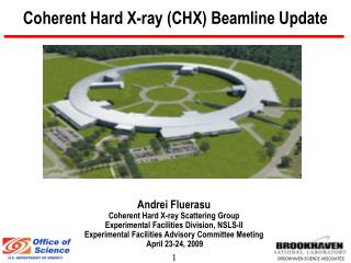
A Hard X-Ray Coherent Scattering Beamline for NSLS-II & SAXS? Alec Sandy, X-Ray Science Division Argonne National Laboratory
Acknowledgements • Design to be discussed today represents work primarily performed by: • Scott Coburn, Brookhaven National Laboratory • Simon Mochrie, Yale University • Ian Robinson, University College London • Many helpful conversations with: • Larry Lurio, Northern Illinois University • Brian Stephenson, Argonne National Laboratory • Mark Sutton, McGill University
Outline • Beamline Mission • Supported Techniques • Lay of the Land • NSLS-II Strengths • Beamline Requirements • Design Philosophy • Conceptual Design • Possible Discussion Items
Beamline Mission • Application of hard (7–12 keV) coherent x-rays to the study of nanoscale dynamics and structure of complex materials • Equilibrium dynamics and fluctuations about the evolution to equilibrium in colloids, polymers, membranes, concentrated proteins, glasses, … • 3-D imaging of microscopic non-crystalline objects such as catalytically active materials, cavities within steel, defect structures in magnetic multilayers, cellular imaging Mark A. Pfeifer, Garth J. Williams, Ivan A. Vartanyants, Ross Harder, and Ian K. Robinson, “Three-dimensional mapping of a deformation field inside a nanocrystal,” Nature 442, 63 (2006) O. G. Shpyrko, E. D. Isaacs, J. M. Logan, Yejun Feng, G. Aeppli, R. Jaramillo, H. C. Kim, T. F. Rosenbaum, P. Zschack, M. Sprung, S. Narayanan, and A. R. Sandy; "Direct measurement of antiferromagnetic domain fluctuations," Nature 447, 68
Supported Techniques • Techniques to be employed • X-ray photon correlation spectroscopy (XPCS) or x-ray intensity fluctuation spectroscopy (XIFS) • X-ray analog of dynamic light scattering • Coherent x-ray diffraction (CXD) • Coherent x-rays and intensity over-sampling to determine the nanoscale structure of micron sized crystals via phase retrieval and inversion • Coherent x-ray diffraction imaging (CXDI) • Coherent x-rays and intensity over-sampling to determine the nanoscale structure of non-periodic objects via phase retrieval and inversion • Lensless imaging, ptychography, CXDI • SAXS • Imaging • Phase contrast imaging • Diffraction enhanced imaging
Lay of the Land • ESRF (6 GeV) • General purpose beamline evolving to XPCS and CXD(I) specialization • Small Q XPCS, considerably less large Q XPCS and CXDI: ID-10 • APS (7 GeV) • Dedicated XPCS beamline but not (yet) CXD/CXDI • Small Q XPCS and considerably less large Q XPCS: 8-ID • CXD (large Q) but limited GU program: 34-ID • CXDI (small Q): ? • SPRing 8 • Little activity • SLS (2.4 GeV) • SAXS, XPCS, CXDI: cSAXS • Sophisticated and advanced detector program but lower energy ring and shorter beamlines • Petra III (6.0 GeV) • Tandem endstations: large Q XPCS, CXD and XPCS and CXDI • Planning phase: 2009–2010 completion—long straights and beamlines • Diamond (3.0 GeV) • USAXS/XPCS branch, CXDI/CXD multiplexed with full-field imaging: I13 • 250 m beamline length • Planning phase: 2010–2011 completion
NSLS-II Strengths • Unprecedented brightness • Both XPCS and CXD remain signal starved techniques • CXD “improves” linearly with brightness • Measurement times from hours to minutes • XPCS “improves” quadratically with brightness • 30× more incident intensity → 1,000× faster dynamics • Existing strong community in soft condensed matter science and a relatively local XPCS community • Soft and hard x-ray coherent x-ray scattering • Existing, innovative detector program coupled to activities on the experiment floor • Leverage for XPCS and CXD detector development • Learn from others’ mistakes and capitalize on several years of operational experience at other 3rd generation coherence-based beamlines • ESRF ID10 (XPCS) and APS 8-ID (XPCS) both originally built to satisfy broad scientific mission
Beamline Requirements • Coherent flux! • Stability • Parasitically fluctuating signals contaminate XPCS time autocorrelation analysis • Parasitically fluctuating signals significantly complicate phase retrieval • Beamtime • Brilliance-hungry techniques so maximize the beamtime delivered to experimental stations • Long beamline • High demagnification focusing for CXD and large Q XPCS • Reduced flux density for radiation sensitive samples • Long small angle XPCS station • “Smart” detectors likely to have larger pixels than today’s • Minimal energy tunability • Above energy of large resonant enhancements
Design Philosophy • KISS – Keep it simple, stupid! • Coherent flux • Select the coherent portion of the x-ray beam as far upstream as possible to eliminate power mitigation issues downstream • Secondary source/pinhole • Preserve the coherence delivered by the undulator and reduce parasitic scattering • Minimize the number of beamline optics • Stability • Minimize the number of beamline optics • Beamtime • Beam comprised of many horizontal coherence lengths—split the beam and feed independent end stations • Limited/infrequent energy tunability • Compatible with split beam operations
Conceptual Design-Secondary Source/Pinhole • Secondary source or pinhole • Extract, in the horizontal, only a coherent fraction of the x-ray beam Sample Undulator D1 D2 S1 S2 Pixel size = p Secondary Source ( 27 m)
Conceptual Design-Secondary Source/Pinhole Sample Undulator D1 D2 • Coherent diffraction over-sampling • λD2/S2 > 2p • Far field • S2/D2 > λ / S2 • Coherent illumination • S2 < λD1/S1 • Use entire source • 2σx < (S1 + S2) D0 / D1 S1 S2 Pixel size = p Secondary Source ( 27 m)
Conceptual Design-Beam Splitting • 2 secondary sources or pinholes in the FOE • Multiplexed operation creates twice as much beamtime • Small horizontal-bounce mirrors used to extract coherent fraction of the beam (in the horizontal) • 2× mirror deflections and long beamline creates sufficient horizontal clearance CXS FOE Beam Splitting Concept-Plan View White beam (WB) Hi-pass filter Pink beam Shutter Slit ½ Slit Mirrors = secondary source or pinhole 12 mrad WB Stop Power-reducing aperture
Conceptual Design-Optical Layout • Simplified version of the optical layout • Undulator • Future upgrade to tandem devices (rather than canted) • Standard operating energy goal 12 keV • Low K value → less power • Less sample radiation damage • High demagnification optics • Kinoform lenses or KB mirrors
Conceptual Design-Floor Layout • Stations • Large Q XPCS and CXD station • High demagnification optics • Diffractometer • Small Q XPCS and CXDI station • Pinhole “SAXS” • Vertically focusing optics • SOE • Monochromators × 2 • Optics? • FOE
Conceptual Design-Small Q XPCS and CXDI Station • Requirements • 50 m from the source and 15 m long × 4 m wide • Pinhole SAXS set-up • 3 or more heavy-duty motorized support tables • High demagnification optics and collimating/guard apertures • Vertical focusing to reduce the vertical coherence length • Collimating and guard apertures • All in vacuum where possible • Sample environment • Flow cells • In vacuum positioning • Long flight path and detector support assembly • Smart detectors • On-the-fly compression, on-board correlation
Conceptual Design-Large Q XPCS and CXD Station Silicon kinoform lens • Requirements • 100 m from source and 6 m long × 6 m wide • Optics table • High demagnification nanofocusing optics • KB mirror, kinoform lens, zone plate • Large load capacity precision diffractometer and/or large load hexapod with ≤ 3 m detector arm • Optical microscopy/fluorescence detectors for sample alignment and registration • Small pixel, high dynamic range direct detection area detector K. Evans-Lutterodt et al., Opt. Express Alio Industries
Some Possible Issues for Discussion • Long beamline • Conceptual design only but significant rethinking required if not allowed • Mirrors or crystals for beam splitting • Split beam vis-à-vis operational support • Canted versus split beam beamlines • Which “imaging” techniques, if any, belong as part of the beamline? • Lensless imaging/ptychography/coherent diffractive imaging • Phase contrast imaging • Diffraction enhanced imaging • Vertical focusing further upstream • Large vertical correlation can not be used so eliminate from the start? • Energy gap • ≥ 7 keV for hard coherent x-ray scattering versus ≤ 2 keV for soft x-ray coherent scattering/imaging • Sample radiation damage • Detectors, detectors, detectors! • Now is the time to worry about detectors