Download
1 / 39
410 likes | 483 Views
Learn about fabrication steps for Bulk and SOI MEMS sensors using Pt material measurement electrodes and oxide nitride layers. Understand lithography processes, alignment requirements, and crucial considerations for sensor material deposition and patterning.

E N D
Bulk and SOI MEMS sami.franssila@aalto.fi
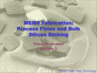
sensor material Pt measurement electrodes oxide Nitride Pt heater Micro hot plate: how many litho steps ? 0. Double side polished <100> wafer • LPCVD nitride • Litho1 on backside for nitride • Nitride RIE & resist strip • Pt sputter • Litho2 of Pt heater • Pt etch & strip • CVD oxide • Litho3 to reveal Pt heater for wire bond • Oxide etch & strip • Pt sputter • Litho4 of Pt measurement electrodes • Pt etch & resist strip • Frontside protection (jig) • Backside KOH etch • Sensor material depo & patterning
<Si> microbridges Backside micromachining Need front-to-back alignment Bridge thickness free variable May use p++ etch stop May use KOH and/or DRIE Front side micromachining Alignment on front only Needs p++ etch stop Depends on p++ selectivity Needs epi for thick bridge Wider bridge depth under larger
Double side alignment Double sided lithography requires DSP wafers (Double Side Polished) Some alignments are critical but not all ! Often the backside structures are large, and not critically aligned to top side features.
Alignment: diffused piezoresistors OK NOT OK Piezoresistors have to be positioned at the maximum defelection region
Capacitive accelerometer Pyrex glass wafer Capacitor 1 Capacitor 2 Pyrex glass wafer
Pressure sensor deflection Simple membrane Not a parallel plate capacitor Hinged membrane: Parallel plate capacitor
heat sink heater resistor thermopile nitride p1 p0 p0 Thermal pressure sensor
SOI and wet etching Dokmeci 2004 IEEE
AFM tips: thru-wafer • SOI wafer with 5-μm thick device layer • thermal oxidation • LPCVD nitride • etch nitride from front side • lithography for the tip • etch oxide • etch silicon isotropically (+ resist strip) • thermal oxidation for tip-sharpening • lithography to define the cantilever • DRIE of device silicon (+resist strip)
AFM tips: thru-wafer (2) • DRIE of device silicon (+resist strip) • thermal oxidation for passivation • lithography for piezoresistors • boron implantation for resistors (+strip) • lithography & etch for contact • boron implantation for contacts (+ strip) • implant activation in RTA • aluminum deposition and patterning • front protection: polyimide spinning • backside nitride litho & etch & strip • backside TMAH anisotropic etch • buried oxide etching • polyimide plasma removal
Membrane chip with Au/Sn solder bumbs air gap acoustic holes Backplate chip with acoustic holes Bonded microphone
Ogawa, Masuda, Takagawa, Kimata: Polarization-selective uncooled infrared sensor with asymmetric two-dimensional plasmonic absorber Opt. Eng. 53(10), 107110 (2014) Etch selectivity between Si and Al: use TMAH etchant
Ogawa, Masuda, Takagawa, Kimata: Polarization-selective uncooled infrared sensor with asymmetric two-dimensional plasmonic absorber Opt. Eng. 53(10), 107110 Isotropic silicon etch, SF6 plasma, or XeF2, selective against metals.
Surface-bulk combo Microphone with thick silicon backplate
Cavity-SOI (C-SOI) (devicelayer 2 – 50 microns) Thermal oxidation Lithography + ox etch Si DRIE Grind + CMP Direct bonding + anneal
C-SOI specifications Device layer 2 – 50 μm BOX thickness0.2 - 4μm Layer transfer?? Antti make up something cool. Cavity depth1 - 300μm Cavity width 1 - 1200μm ± 10 % Handle wafer 200 - 1000μm
Cavity dimensions vs. SOI thickness Luoto et al. "MEMS on cavity-SOI wafers." Solid-State Electronics 51.2 (2007): 328-332.
C-SOI MEMS Solid-State Electronics 51 (2007) 328–332
oxide Al electrode Si membrane air cavity ground electrode Cavity-SOI resonator • DSP silicon handle wafer • Lithography of air cavity • DRIE of silicon & strip PR • Cleaning • Thermal oxidation • Bonding with a bulk wafer • Thinning by KOH etching • Polishing • Al sputtering • Litho • Al etch & strip • CVD oxide
C-SOI: No need for release etching
C-SOI: alignment • Cavity and otherfront-side structureswillbecoveredbythedevicesilicon • Alignmenthas to bedonewithbacksidetargets. • Backsidetargetcanlaterbetransfered to front.
CMOS-MEMS integrated CMOS first MEMS in silicon MEMS in IC thin films MEMS thin films specifically MEMS first plug-up SOI polysilicon thin film MEMS Integrated processes
b a CMOS first, no additional films a) thin film MEMS by front side dry plasma release; b) single crystal silicon MEMS byDRIE
CMOS-MEMS Piezoresistive Accelerometer Khir Sensors 2011, 11, 7892-7907;
MEMS packaging Capping wafer Thin film sealing
MEMS reliability 1. Solid state devices, no cavities or moving parts. 2. Devices with channels/cavities but no moving parts. 3. Devices with bending/moving but non-contacting parts. 4. Devices with contacting surfaces. 5. Devices with contacting and rubbing surfaces.
MEMS commercialization • Solid state devices, no cavities or moving parts. MAJOR INDUSTRY. 2. Devices with channels/cavities but no moving parts. INK JET PRINTERS
3. Devices with bending/oscillating but non-contacting parts. Pressure sensors Accelerometers Microphones IR detectors cMUTS, pMUTS Widely available.
4. Devices with contacting surfaces. Some available. Wafer level packaging helps a lot. Micromirrors Microvalves RF switches
5. Devices with contacting and rubbing surfaces Gears Turbines Pop-up mirrors None available. Wafer level packaging does not help.
https://media.nature.com/m685/nature-assets/micronano/2015/micronano20155/images_hires/micronano20155-f10.jpghttps://media.nature.com/m685/nature-assets/micronano/2015/micronano20155/images_hires/micronano20155-f10.jpg