Download
1 / 8
80 likes | 164 Views
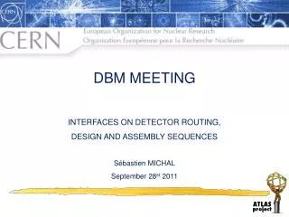
DBM Interfaces Meeting. D. Giugni / INFN Milano. Project framework. The 4 DBM telescopes (per side) are hold by the BPSS (Pixel Beam Pipe Services Support) They are supported by the “cruciform” at about Z=800mm

E N D
DBM Interfaces Meeting D. Giugni / INFN Milano DBM Interfaces Meeting 2011-09-28
Project framework • The 4 DBM telescopes (per side) are hold by the BPSS (Pixel Beam Pipe Services Support) • They are supported by the “cruciform” at about Z=800mm • The services, both cooling and electrical, are routed along ONE nSQP (the C34). C34 nSQP BPSS Vertical Direction DBM Interfaces Meeting 2011-09-28
Cooling • 1 Pixel loop = 220W @ -25C • Max Press = 13bara • Evaporation temperature -15C<T<+20C PP1 DBM PP0 DBM Interfaces Meeting 2011-09-28
Electrical Services • DBM looks like an IBL half stave with 4x3=12 FE chips instead 16. • Both power and readout will belong to IBL readout • Power lines and DCS reach the IBL AXON Connector on the IDEP • The signal lines (DTO, CLK and CMD) reach the IBL optobox where a dedicated Optoboard reads-out the signals. Since an IBL OptoBoard can handle 16FE chips, the 16-12=4 extras can be used to extract the trigger. DBM Interfaces Meeting 2011-09-28
Scopes and goals of the meeting • Main scope is to define the interfaces: • Connector type, number and position next to the DBM telescopes • Position of the fitting for the cooling line. • ...and who designs what: • PP0 Boards [CERN] • Power and Readout Bundles [CERN] • Connector to the OptoBox (Conn. Board) [CERN] • DBM Structure [Toronto] • Boiling Channel [Toronto] • Thermal coupling [Toronto] • DBM Flex [?] C34 nSQP DBM Interfaces Meeting 2011-09-28
Documentation available • DBM Top level block connectivity ATL-IP-ES-0178 [Jacek] • DBM Top Level Schematic ATL-IP-ES-0184 [Jacek] • DBM Signal & Cable Board Schematic ATL-IP-ES-0183 [Jacek] • IBL Connector Board Schematic ATL-IP-ES-0176 [Steven] • IBL Connector Board Gerber Files ATL-IP-ES-0177 [Steven] • IBL OptoBoard Schematic (in the INDICO Agenda Material Section) [Shane] DBM Interfaces Meeting 2011-09-28
Prototypes Production Plan • Hope to get from this meeting the green light for the design: • Interfaces (at PP0 and at PP1). • Cooling fittings location • Cooling coupling • Connectors • Boards • Services functionality. • Wires type, number and connectivity. • Procurement • Wires, Shield, Braids (4 wks leading time), • PP0 boards (6wks) • IBL Connector Board (4wks) • AXON Connector and pinout (?) DBM Interfaces Meeting 2011-09-28
Prototypes Production Plan (2) • Middle November can start producing the fist full DBM harnesses. • Production time (bundling and soldering) ~2 wks • If something goes wrong there is time for a second try before Xmas DBM Interfaces Meeting 2011-09-28