Download
1 / 15
150 likes | 218 Views
Explore the V0 detector collaboration project, featuring segmentation of V0A and V0C arrays, simulated performances, optimalization for multiplicity measurement, counters design, electronics specifications, and mechanics milestones.

E N D
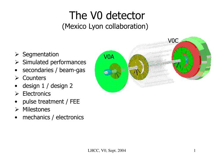
V0C V0A The V0 detector(Mexico Lyon collaboration) • Segmentation • Simulated performances • secondaries / beam-gas • Counters • design 1 / design 2 • Electronics • pulse treatment / FEE • Milestones • mechanics / electronics LHCC, V0, Sept. 2004
Segmentation of the arrays • Two arrays V0A and V0C • 2 x 32 channels • segmentation: 8 sectors x 4 rings • Pseudo-rapidity windows: • = 0.5-0.6/ring LHCC, V0, Sept. 2004
V0C V0A Secondaries • Performances very degraded by secondaries produced in materials • No optimalization of the V0 for multiplicity measurement • Pb-Pb Hijing events (b < 11 fm) • correlations Mch of events / Mch • detected by V0 rings • increase of hits by a factor two: • 4000 MIP across each ring (8000 across the ring 1 of V0C) • Nevertheles, central and/or semi-central collisions can be selected by the FEE on the base of the total integrated charge provided by the counters • Efficiency of triggering: 83% in pp (inelastic) LHCC, V0, Sept. 2004
p-gas background • The V0 should be able to filter a large part of the p-gas effect • ‘close p-gas’: Hijing (198 kHz) ‘halo’: file used by LHCb (47 kHz) pp physics: Pythia (200 kHz) • Gaussian vertex (5.3 cm) and time resolution (1 ns) • A cut at 11 ns: • rejection depends on the relative rates of the two components • 99% of rejected beam gas in the • present case LHCC, V0, Sept. 2004
Counters Design 2 Design 1 Teflon foil Teflon foil connector connector WLS fibres WLS fibres PM optical fibres PM optical fibres • Counters made of • 2 cm BC404/BC408 scintillator • 1 mm BCF9929A(s.c.)/BCF9929A(d.c.) WLS fibres • 1.1 mm BCF98(d.c.) optical fibres • Teflon foil as envelope LHCC, V0, Sept. 2004
Results • Design 2 applied to V0C elements • 2 cm BC408 scintillator • 1 mm BCF9929A(s.c.) WLS fibres • 5 m of BCF98(d.c.) optical fibres • Present performances (MIP): 28 – 34 – 42 p.e. optical fibre 500 – 600 ps 800 20 • Design 1 applied to V0A elements • 2 cm BC404 scintillator • 1 mm BCF9929A(d.c.) WLS fibres • 3 m of BCF98(d.c.) optical fibres • Present performances (MIP): • For the RB26 side, theintegration requires short transition from edge of counter to clear fibres • Only possible with design 2 • Improvement with BC404/BCF(d.c.)? • measures in progress • Design 1 provides a similar network of fibres to any scintillating track, whatever its location on the counter is • timefluctuation minimized, better σtime • Adapted for large tiles • Adopted for V0A at RB24 side
V0A array PM connector bar all fibres from a sector fibres gathered in 4 bundles fiber length 3 m LHCC, V0, Sept. 2004
V0C array fiber length 5 m 24 bundles in a duct for 2 sectors box in carbon-fibre 12 connectors rings 3 and 4 in 2 pieces to minimize time fluctuations
Electronics • Requirements • MIP dynamic range: 1 to 500 with 98% of acceptance for the MIP • signal dynamic range: close to 1000 (minimum of3 mVachieved) • charge information (0.6 < Q < 600 pC), time (σtime < 1 ns) • Mesh PMT with amplification (‘shoebox’) of the signal before its transmission (25 m of Cu-cables) to FEE • FEE 100% of life time • made of three PCBs: • CIU: charge and time digitization, pre-process of triggers • CCIU: final trigger signal, collection of the data • TTCIU: interface FEE/TTC • Concept finalized by the end of 2004 LHCC, V0, Sept. 2004
data from V0C time buffer X 4 HPTDC (8 ch/chip) L1 buff data from V0A DAQ data charge low M hit L2 individual offset THR V0A L0 compensation 1 sum for 4 DISC. + BBA (BBC) BB MB triggers each ring x 32 anodes buffer buffer 1 sum for 4 BGA(BBC) BBA (BGC) + DISC. each ring BG MB triggers adjustable windows adjustable windows (step of 20ps, range of 10 ns) (.5 to 12ns, step of .5ns) BGA BGC multiplicity triggers THRmult. (V0C) buffer from V0C ADC from V0C 4 4 5 triggers, eg : 4 1 sum for - minimum bias + 4 L0 DAQ - beam/gaz (right) FPGA each ring buffer - beam/gaz (left) THRcharge 4 - multiplicity ADC - centrality BC programmable programmable centrality triggers L0 thresholds from V0C integration gate width charge (from 3ns to 36ns, 3ns step) CIU board LHCC, V0, Sept. 2004
V0A THR -11 ns buffer 1 sum for 4 l t DISC. BGA + each ring x 32 anodes buffer 1 sum for 4 BBA + DISC. each ring +11 ns adjustable windows adjustable windows (step of 20ps, range of 10 ns) (.5 to 12ns, step of .5ns) BGA bbc -3 ns A BGC BGC & + bba BB C BBC + A +3 ns THRmult. & V0C C Multiplicity trigger Minimum-bias triggers • Starting from the discriminator signal • BB signal detected in time windows centered at +11 ns (V0A) and +3 ns (V0C) • BGAsignal detected in time windows centered at -11 ns (V0A) and +3 ns (V0C) • BGC signal detected in time windows centered at +11 ns (V0A) and -3 ns (V0C) LHCC, V0, Sept. 2004
V0 mechanics milestones • End 2004: • March 2005: sector ‘0’ of V0A (Mexico) and V0C (Lyon) (construction and test) PRR submission • October 2005: V0C commissioning, PMT characterization (Lyon) • End 2005: V0A commissioning, PMT characterization (Mexico) • April 2006: • June 2006: V0C installation in ALICE • End 2006: V0A installation in ALICE p.e./MIP PMTgain arrays, fibre bundles, PMT mechanics • Responsibles: Mechanics: J.Y. Grossiord (Lyon), XXXX (Mexico)
V0 electronics milestones • End 2004: electronics concept finalization (PMT, ‘shoebox’, FEE) CIU design prototype test • March 2005: • October 2005: CCIU and TTCIU design prototype test PRR submission • End 2005: CIU, CCIU, TTCIU electronic scheme • April 2006: electronics design ready for realization • June 2006: electronics construction • End 2006: electronics test, calibration, connection to CTP electronics ready for installation in ALICE • Responsibles: Electronics: Y. Zoccarato
V0 milestones • End 2004: electronics concept finalization (PMT, ‘shoebox’, FEE) CIU design prototype test • March 2005: sector ‘0’ of V0A (Mexico) and V0C (Lyon) PRR submission • October 2005: V0C commissioning, PMT characterization (Lyon) CCIU and TTCIU design prototype test PRR submission • End 2005: V0A commissioning, PMT characterization (Mexico) CIU, CCIU, TTCIU electronic scheme • April 2006: electronics design ready for realization • June 2006: V0C installation in ALICE electronics construction • End 2006: V0A installation in ALICE electronics test, calibration, connection to CTP electronics ready for installation in ALICE • Responsibles: Electronics: Y. Zoccarato Mechanics: J.Y. Grossiord (Lyon), XXXX (Mexico)