Download
1 / 25
250 likes | 270 Views
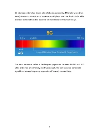
Explore the evolution and challenges of silicon millimeter-wave integrated circuits for various applications like wireless, radar, consumer electronics, and military markets. Learn about key challenges, test measurements, and exemplary silicon circuits.

E N D
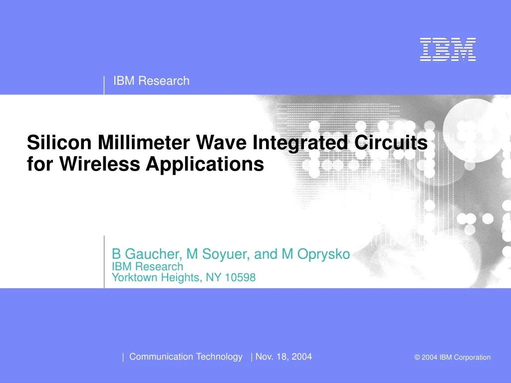
B Gaucher, M Soyuer, and M Oprysko IBM Research Yorktown Heights, NY 10598 Silicon Millimeter Wave Integrated Circuits for Wireless Applications
Outline • Silicon is ready for mmwave frequencies • Millimeter wave applications • Applications • Challenges • Lets look at 60 GHz WLAN as an example • Exemplary silicon circuits • Looking at higher frequencies • Exemplary circuits (VCOs, LNAs, PA’s…) • And what can we expect silicon mmwave ICs to cost ? • Summary and concluding remarks
Evolution of SiGe HBTs CMOS lithography • Significant improvement in Ft/Fmax with each generation 0.13um 1.2v 8HP mmwave 200/180GHz/1.7V 200/250GHz 7HP 0.18um 1.8v 120/100 GHz/1.8V 120/125GHz Radar (24 GHz Automotive) Wirleline (40 GbpsOC768) wireless 6HP 6HP 0.25um 2.5v 47/60 GHz/3.3V 0.5/0.35um 3.3, 5v wireless Legend High Speed NPN Ft /Fmax (MAG)/ BVceo Ft/Fmax (Unilateral Gain) 5HP 0.5um 3.3v 50/50 GHz/3.3V 2003 2004 1997 1998 1999 2000 2001 2002
Increasing speed of silicon technologies • “…if it can be done in silicon; it will be done in silicon…” • Focus: • on large V swing • High power • Small scale integration • 10 & 40 Gbps hardware shipping • 1st designs targeting 80 to100 Gbps • 1st designs targeting mmwave • Medium scale integration • 1 & 10 Gbps hardware shipping • 1st publications targeting 40 Gbps • 1st publications targeting 60GHz • Large scale integration
Outline • Silicon is ready for mmwave frequencies • Millimeterwave applications • Applications • Challenges • Lets look at 60 GHz WLAN as an example • Exemplary silicon circuits • Looking at higher frequencies • Exemplary circuits (VCOs, LNAs, PA’s…) • And what can we expect silicon mmwave ICs to cost ? • Summary and concluding remarks
IEEE Standards Headed Toward 60GHz? • 802.15.3 has the potential to continue the wireless chase, UWB, 60 GHz • WLAN/WPAN may extend its speed advantage 802.11n is addressing this space WLAN may go with 60GHz given it has 5GHz of bandwidth, world wide • Not likely to see real 480-1000Mbps HW until >2006. 60 GHz 802.11n UWB BT 2.0 BT1.0 Drivers include: Frequency allocation WW, bandwidth, capacity, power, cost, reliability
Commercial Apps Millimeter Wave Applications • 802.11x Markets • WLAN • WPAN • Automotive Radar at 77/79 GHz • Telecommunications backhaul • Consumer • Wireless Last Mile … • Military Markets (38, 60, 94 GHz) • Future Combat systems • Secure communications • Satellite Communications • Military phased array markets • Reconfigurable, software definable systems Commercial Integrated Wireless Military Military Apps
High-Speed Wireless Need Driven by Consumer Apps Low power, short range 100-500Mbps link • Consumer electronics • Replacement for 1394 Fire Wire and other cables • Potential for 150M consumer electronic devices, such as TVs, home automation camera/camcorder, game consoles, music players etc. by 2009. • Computer & peripherals • Replacement for USB, monitor cable, parallel ports and other cables – • Potential for 100M computers and peripherals by 2009. • Other application needs outside home • Healthcare, SOHO, industrial control, wireless sensor network, smartphones, last mile access, positioning & measurements (asset management), radar… Computer applications Consumer electronic applications
Key Challenges for Silicon Millimeter-Wave Circuits • Lossy silicon substrate poor isolation, lower Q components. • Need for a predictive design kit such that 1st pass success is achievable. • Accurate transmission line and transistor models. • Accurate parasitic extraction (distinction between device and parasitic blurred). • Silicon CAD tools (e.g. Cadence with EM simulation). • Need to yield circuits in the silicon environment density requirements on metal, poly, and active layers. Effect on RF performance of passives? • Achieving very high levels of integration in silicon while maintaining MMW functionality.
The Challenges of Test: On-Wafer mmWave Circuit Measurements Power Characterization (50-75GHz, 75-90GHz): From VNA Challenges at MMW frequencies: To VNA - on-wafer characterization - cable losses • differential measurements Input Balun Output Balun Noise Characterization (50-75GHz, 75-90GHz): S-Parameters (40MHz to 110GHz): Low Noise Downconverter 110GHz VNA system diplexers to Noise Figure Meter Noise Source MMW modules
60GHz Link Budget LOS: line-of sight OLOS: obstructed (by person) LOS 1Gbps@20M 1Gbps@3M
An Example of a Conventional Architecture Using SiGe Heterodyne Tx • Key Building Block Circuits • Low-Noise Amplifiers • Mixers • Voltage-Controlled Oscillators • Power Amplifiers PA 500MHz + 90° ÷2 PO=+10dBm x3 VCO ÷N ÷N Direct-Convert Rx x3 Pre-Amp LNA 500MHz 90° Gain=16dB NF=15dB Gain=17dB NF=4 dB Gain=33dB, NF=6dB Circuits built & tested
20 Gain 18 16 dB 14 12 10 8 NF 6 4 2 Frequency (GHz) 0 58 59 60 61 62 63 64 65 Key 60 GHz Circuits Already Built and Tested: Power Amplifier Low Noise Amplifier Icc = 6 mA Vcc = 1.8 V NF (at 60GHz) = 3.3-3.7 dB NF (at 63 GHz) =4.2-4.6 dB Mean NF = 3.7 dB • Gain = 10.8 dB • P1 dB = 11.2 dBm • Psat = 16.2 dBm • 130 mA at 2.5V Direct Conversion Mixer Voltage Controlled Oscillator • VCO Meas’d performance • -102 dBc/Hz @ 1MHz • 8mA at 3V • Pout -11 dBm • First Gilbert-cell mixers at 60 GHz. • Highest integration level for any technology at 60 GHz. • 80 transistors • 43 transmission lines or inductors • Meas’d performance comparable or exceeding GaAs • NF (< 15 dB), • conversion gain (> 16 dB), • Vcc = 2.7V • power (150 mW “core”) -102dBc/Hz @ 1MHz ISSCC 2004 Output Spectrum / Phase Noise
Antenna Buffer LNA1 LNA2 (Different Chip) (Active Balun) Gilbert Buffer Mixers LO Pilot Input Differential Branch- 19.67 - Line Directional 21.33 GHz Buffer Coupler Frequency Tripler Termination Buffer Resistor 60-GHz Direct-Conversion Quadrature Downconverter World’s first 60GHz silicon direct down conversion mixer • First Gilbert-cell mixers at 60 GHz. • Highest reported integration level for any technology at 60 GHz. • 80 transistors • 43 transmission lines or inductors • Performance comparable or exceeding GaAs • NF (< 15 dB), • conversion gain (> 16 dB), • power (150 mW “core”) 1.9mm x 1.65mm
What are the next steps ? • Make mmwave components look to users just like other low frequency semiconductor components • Broaden the number of potential users worldwide • A new generation of mmwave applications • Demonstrating • Monolithic Tx chip and • Monolithic Rx chip • Low cost package which does not require end users to have sophisticated mmwave test and packaging skills • Plastic package • Chip • Antenna
60-GHz Receiver and Transmitter Receiver Baseband BB Amp IF Mixer Image-rejectLNA DAC IF Amp I Input 59-64 GHz ÷2 x3 Q ÷ 32 PLL LPF CP PFD Transmitter I x3 ADC PA Output 59-64 GHz ÷2 Q IF Amp Image-reject Driver IF Mixer
Mixer & IFVGA Tripler IN Tripler Driver Amp Mixer & IFVGA PA LNA Out IF Mix PLL PLL IF Mix RCLK BB Amp BB Amp Baseband Inputs Baseband Outputs 60-GHz Transmitter Layout Size: 4.0 x 1.5 mm2 60-GHz Receiver Layout Size: 3.4 x 1.6 mm2
Concept of Fully Integrated MMW Transceiver • IBM SiGe technology with >200GHz fT/fmax • highly integrated silicon based MMW transceiver ICs low-cost package including fully integrated MMW transceiver and antennas Quarter Sized Transceiver • small wave length (e.g. ~ 5mm @ 60GHz) • antenna in package • no MMW signal off or on package
Outline • Silicon is ready for mmwave frequencies • Millimeter wave applications • Applications • Challenges • Lets look at 60 GHz WLAN as an example • Exemplary silicon circuits • Looking at higher frequencies • Exemplary circuits (VCOs, LNAs, PA’s…) • And what can we expect silicon mmwave ICs to cost ? • Summary and concluding remarks
SiGe integration & volumes CMOS integration & volumes …and what can we expect silicon mmwave ICs to cost ? • Keys to driving cost…look at 802.11x WLANs as an example • Establishing an industry standard (802.11b) • Generating volumes: • Chip sets “everywhere” (PCs, enterprise & SOHO access points, adaptor cards, etc….) • “riding” the silicon cost curve • Silicon integration (1st in SiGe, then in CMOS) (chip set includes RF transceiver, PA, BB, MAC) • Mmwave ICs in SiGe can be expected to follow similar historical trends !
Outline • Silicon is ready for mmwave frequencies • Millimeter wave applications • Applications • Challenges • Lets look at 60 GHz WLAN as an example • Exemplary silicon circuits • Looking at higher frequencies • Exemplary circuits (VCOs, LNAs, PA’s…) • And what can we expect silicon mmwave ICs to cost ? • Summary and concluding remarks
….this is only the beginning ! CMOS lithography Quasi-optical Band Next Gen • New transistors and passives open up bands to 150 GHz ! • Imaging • Wireless measurements • ???? Target 300GHz/TBD 0.13um 1.2v 8HP mmwave 200/180GHz/1.7V 200/250GHz 7HP 0.18um 1.8v 120/100 GHz/1.8V 120/125GHz Radar (24 GHz Automotive) Wirleline (40 GbpsOC768) wireless 6HP 6HP 0.25um 2.5v 47/60 GHz/3.3V 0.5/0.35um 3.3, 5v wireless Legend High Speed NPN Ft /Fmax (MAG)/ BVceo Ft/Fmax (Unilateral Gain) 5HP 0.5um 3.3v 50/50 GHz/3.3V 2003 2004 1997 1998 1999 2000 2001 2002
Summary & concluding remarks • “…anything that can be done in silicon; will be done in silicon…” • SiGe enables low power & high level integration not possible in III-V technologies • We have demonstrated key mmwave building block circuits in SiGe with performance suitable for enabling the 60 GHz ISM band • highest integration direct-conversion mixer • high performance V-band LNAs • power amplifiers • Historical silicon “take down” curves suggest attractive costs for mmwave transceivers based on • Silicon integration • volume growth • We are witnessing the rebirth and renaissance of millimeter wave technology and applications enabled by a new generation of silicon