Download
1 / 37
370 likes | 528 Views
ECE 697F Reconfigurable Computing Lecture 11 FPGA-Based System Design. Topics. Basics of sequential machines. Sequential machine specification. Sequential machine design processes for FPGAs. FSM structure. Constraints on structure. No combinational cycles.

E N D
ECE 697FReconfigurable ComputingLecture 11FPGA-Based System Design
Topics • Basics of sequential machines. • Sequential machine specification. • Sequential machine design processes for FPGAs
Constraints on structure • No combinational cycles. • All components must have bounded delay • FPGAs benefit from many flip flops and predictable timing • Asynchronous circuits difficult to implement in FPGAs
Synchronous design • Controlled by clock(s). • State changes at time determined by the clock. • Inputs to registers settle in time for state change. • Primary inputs settle in time for combinational delay through logic. • Machine state is determined solely by registers. • Don’t have to worry about timing constraints, events outside the registers.
Non-functional requirements and optimization • Performance: • Clock period is determined by combinational logic delay. • Area: • Combinational logic size usually dominates area. • Energy/power: • Often dominated by combinational logic. • May be improved by latching values.
D D D D D D Q Q Q Q Q Q Register-transfer structure • Registers fed by combinational logic: Combinational logic
Counter state transition graph • Cyclic structure: 1/1 1/2 1/7 0 1 6 7 … 1/0
Example: 01 string recognizer • Recognize 01 sequence in input string: recognizer 0 0 0 0 1 1 1 0 0 0 1 1
Sequential machine definition • Machine computes next state N, primary outputs O from current state S, primary inputs I. • Next-state function: • N = (I,S). • Output function (Mealy): • O = (I,S).
Reachability • State is reachable if there is a path from given state. • May be created by state encoding: s0 s1 s2 s3
Internal connections External connections Networks of FSMs • Functions can be built up from interconnected FSMs: I1 I2 x M1 M2 y O1 O2
D D Q Q Illegal composition of Mealy machines Combinational logic Combinational logic
Communicating FSM states 0/0 s1 s3 -/1 1/1 1/0 -/0 s2 s4 0/0 M1 M2
Product machine • Two connected machines: R S i1 o1 o2 i2
0 R1 0 S1 1 0 R2 1 S2 0 0 R3 0 S1 0 0 R3 0 S1 0 Behavior of connected machines R S i1 o1 o2 i2
Forming product machine • Form Cartestian product of states: • R1S1, R1S2, R2S1, R2S2, R3S1, R3S2. • For each product state, determine the combined behavior of each product transition: • Required inputs. • Produced output. • Next product state.
Encoding a shift register • Symbolic state transition table for shift register:
Bad encoding • Let S00 = 00, S01 = 01, S10 = 11, S11 = 10. • Logic: • Output = S1 S0’ + S1’ S0 • N1 = I • N0 = I S1’ + I’ S1
Good encoding • Let S00 = 00, S01 = 01, S10 = 10, S11 = 11. • Logic: • Output = S0 • N1 = I • N0 = S1
Bus interfaces • Requirements: • High performance. • Variable signal environment. • Techniques: • Asynchronous logic. • Handshaking-oriented protocols.
Timing diagrams 1 0 a changing stable b Timing constraint c
Asynchronous logic • Distribute timing information with values. • No global clock. • Clock signal paths must have the same delay as data values.
adrs D Q Latching an asynchronous signal adrs adrs_ready
Hold time Setup time Asynchronous timing constraints • Must satisfy setup, hold times. adrs
requirements constraints Bus system design • Requirements: • Imposed by the other side of the system. • Constraints: • Imposed by this side of the system. a b
D D Q Q Views of the bus • Hardware: a b Combinational logic
a b D D Q Q Combinational logic Views of bus system, cont’d. • Timing diagram: x y x y
Bus protocols • Basic transaction: • four-cycle handshake. a b
Handshake machine • Each side is an FSM (possibly asynchronous): a b Go enq enq 0 1 0 1 ack ack ack
Advanced transactions • Multi-cycle transfers: • Several values on one handshake. • May use implicit addressing.
PCI bus • Used for box-level system interconnect. • Two versions: • 33 MHz. • 66 MHz. • Supports advanced transactions.
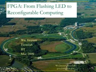
Platform FPGAs • Put all the logic for a system on one FPGA. • Requires large FPGAs plus: • Specialized logic: • I/O support; • memory interface. • CPUs.
Example: Virtex II Pro • Major features: • Large FPGA fabric. • High-speed I/O. • PowerPC.
Virtex II Pro High-speed I/O • Rocket I/O: • parallel/serial or serial/parallel transceiver. • Clock recovery circuitry. • Transceivers for multiple standards: Gigabit Ethernet, Fibre Channel, etc. • Programmable decoding features. • Interface to FPGA fabric.
Virtex II Pro CPUs • Up to 4 PowerPC 405s per chip: • 5 stage pipe, static branch prediction, etc. • Separate instruction, data caches. • MMU. • Timers. • Scan-based debug support.
Summary • Understanding design styles is important for FPGA based design • Synchronous design forms an important role • Various interfaces allow FPGAs to communicate with the outside world • Bus timing forms a key component • State machine interaction allows for complex testing and debugging • Verification plays an important role in FPGA test • Both logic and delay testing have roles