Download

1 / 37
420 likes | 725 Views
Full Adder. Verilog(HO: wires/ regs , always) Section 4.5 (Full adder). Schedule. Outline. Observations Wire Versus reg Using always @() Blocking statement Non-Blocking Statement Full Adder. Observations. V IL ,V IH , V OH , V OL Power Supply of a Chip Orientation of a chip

E N D
Full Adder Verilog(HO: wires/regs, always) Section 4.5 (Full adder)
Outline • Observations • Wire Versus reg • Using always @() • Blocking statement • Non-Blocking Statement • Full Adder
Observations • VIL,VIH, VOH, VOL • Power Supply of a Chip • Orientation of a chip • Outputs of the test bench • Context of a variable
Module Template module module_name ( , , ) endmodule Input, output wires reg Program Body
Wires (1): Connect Gates w1 connects the output of G1 to an input of G3.
Wires (2): Connect input/output ports to elements within a module IMPORTANT: wire is the only legal type on the left hand side of = in an assign statement. s and c are both wires in this example.
Error Message correct! error!
Wires (3): Not on the LHS of = or <= t_clock is a reg. This is OK.
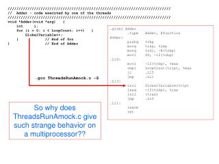
Error Message module half_adder_tb (X,Y); //output, wires, regs output X,Y; wire X,Y; wire S,C; regt_X[10000:0]; regt_Y[10000:0]; regt_clock; reg [31:0] vectornum; integer fp; …. always @(negedget_clock) begin X<=t_X[vectornum]; Y<=t_Y[vectornum]; vectornum<=vectornum+1; end ….. endmodule
reg • All outputs generated by the always block must be declared to be of type reg. • reg is used to suggest that the values behaves like a variable that might be stored in a register.
module....endmodule module fig3p37 (A,B,C,D,E); output D,E; input A,B,C; wire w1; and G1(w1,A,B); not G2(E,C); or G3(D,w1,E); endmodule Always start the verilog program with the keyword pair module…endmodule The keyword module must always be terminated by the keyword endmodule.
module half_adder_tb (X,Y); //output, wires, regs output X,Y; reg X,Y; wire S,C; regt_X[10000:0]; regt_Y[10000:0]; regt_clock; reg [31:0] vectornum; integer fp; …. always @(negedget_clock) begin X<=t_X[vectornum]; Y<=t_Y[vectornum]; vectornum<=vectornum+1; end ….. endmodule
always statement The sensitivity list contains a list of all signals that will affect the outputs generated by the always block.
always @(*) module half_adder_tb (X,Y); //output, wires, regs output X,Y; reg X,Y; wire S,C; regt_X[10000:0]; regt_Y[10000:0]; regt_clock; reg [31:0] vectornum; integer fp; …. always @(negedget_clock) begin X<=t_X[vectornum]; Y<=t_Y[vectornum]; vectornum<=vectornum+1; end ….. endmodule * in the sensitivity list will automatically include all signals on the right side of your statements always @(*) can be used when you want your elements to change their values as one or more of its inputs change. always@ can be used with either non-blocking statement (if you want to execute statements in parallel) or blocking statement (if you want to execute statements sequentially)
Why using always @(*) (incorrect!) (Desirable)
Blocking (=)Statements “when the sensitivity list is satisfied, B gets A, C gets B, and D gets C.” But, by the time C gets B, B has been set to A. Likewise, by the time D gets C, C has been set to B, which, as we stated above, has been set to A. Important: Statements with = executes sequentially.
(<=) Non-Blocking Statements Important: B gets A’s value, C gets B’s old value, and D gets C’s old value
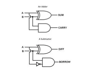
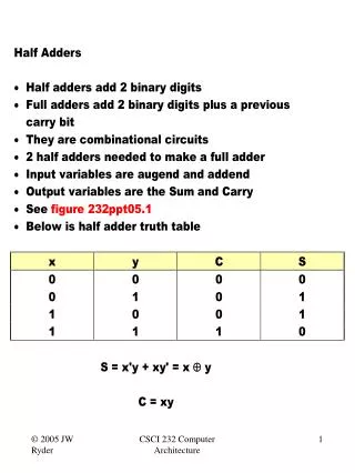
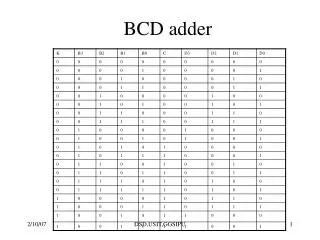
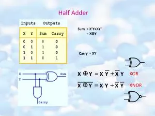
Truth Table for a Full Adder carry-in
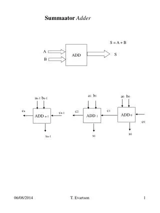
Implementation of a Full Adder (carry-in)