Download
1 / 20
200 likes | 226 Views
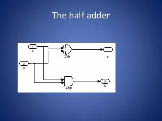
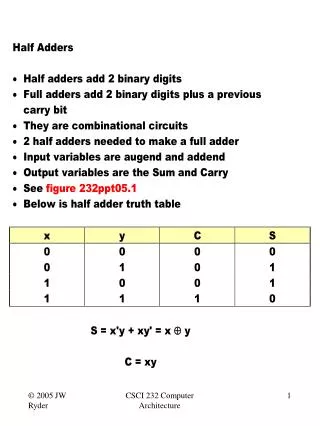
1. Figure 10.1 Truth table and schematic diagram for a binary half-adder. Figure 10.2 Truth table and schematic diagram for a binary full adder. Figure 10.3 Full adder implemented with two half-adders, by means of two 4-input multiplexers, and as two-level gate network.

E N D
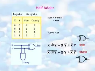
Figure 10.1 Truth table and schematic diagram for a binary half-adder. Computer Architecture Parhami
Figure 10.2 Truth table and schematic diagram for a binary full adder. Computer Architecture Parhami
Figure 10.3 Full adder implemented with two half-adders, by means of two 4-input multiplexers, and as two-level gate network. Computer Architecture Parhami
Figure 10.4 Ripple-carry binary adder with 32-bit inputs and output. Computer Architecture Parhami
Figure 10.5 The main part of an adder is the carry network. The rest is just a set of gates to produce the gand psignals and the sum bits. Computer Architecture Parhami
Figure 10.6 The carry propagation network of a ripple-carry adder. Computer Architecture Parhami
Figure 10.7 A 4-bit section of a ripple-carry network with skip paths. Computer Architecture Parhami
Figure 10.8 Driving analogy for carry propagation in adders with skip paths. Taking the freeway allows a driver who wants to travel a long distance to avoid excessive delays at many traffic lights. Computer Architecture Parhami
Figure 10.9 Schematic diagram of an initializable synchronous counter. Computer Architecture Parhami
Figure 10.10 Carry propagation network and sum logic for an incrementer. Computer Architecture Parhami
Figure 10.11 Brent-Kung lookahead carry network for an 8-digit adder, along with details of one of the carry operator blocks. Computer Architecture Parhami
Figure 10.12 Brent-Kung lookahead carry network for an 8-digit adder, with only its top and bottom rows of carry operators shown. Computer Architecture Parhami
Figure 10.13 Blocks needed in the design of carry-lookahead adders with four-way grouping of bits. Computer Architecture Parhami
Figure 10.14 Carry-select addition principle. Computer Architecture Parhami
Figure 10.15 Multiplexer-based logical shifting unit. Computer Architecture Parhami
Figure 10.16 The two arithmetic shift instructions of MiniMIPS. Computer Architecture Parhami
Figure 10.17 Multistage shifting in a barrel shifter. Computer Architecture Parhami
Figure 10.18 A 4 × 8 block of a black-and-white image represented as a 32-bit word. Computer Architecture Parhami
Figure 10.19 A multifunction ALU with 8 control signals (2 for function class, 1 arithmetic, 3 shift, 2 logic) specifying the operation. Computer Architecture Parhami