Download
1 / 65
660 likes | 720 Views
Learn about the behavior and performance of cold-formed steel frames, explore performance-based design criteria, seismic performance, and ductility in civil engineering. Discover why CFS systems are becoming popular globally.

E N D
Prof. Kamal Bajoria Civil Engineering Department Indian Institute of Technology Bombay World Congress and Exhibition on Construction and Steel Structure 18 Nov 2015 Dubai UAE Performance Based Design of Cold-formed Steel Frames
Overview • Introduction • Objectives of the study • Performance based design • Behaviour of cold-formed steel • PBD of CFS Barrack frames • Conclusions • Future Scope
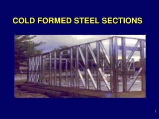
Introduction • CFS frame is semi-rigidly connected frame. • Becoming famous structural system in European countries, Australia, Canada, US and some Asian countries for low residential constructions. • The reasons for growing applications are: i) high strength to weight ratio ii) high stiffness iii) easy and fast erection and installation • Being light in weight, it can replace timber construction in EQ regions.
But there is still a refrain among construction engineers and designers to use it at large scale. • CFS sections are thin-walled sections which are very prone to sectional buckling – local buckling, distortional buckling, lateral-torsional buckling. • Thin-walled sections being slender and semi-rigidly connected at joints gives very low ductility. • So, there is need for performance evaluation of CFS structures at global and local level. • Till now, many researches have been done to evaluate the performance of CFS and to improve its ductility.
Performance Based Design • Relatively new concept of design in civil engineering. • Goal- To produce structures that have predictable seismic performance under multiple levels of earthquake intensity. • In order to do so, it is important that the behaviour of the structures is targeted in advance, both in elastic as well as the inelastic ranges of deformation. • The deformation of member strength hierarchy, failure mechanism and structure strength become the primary elements of a performance-based design procedure.
Design criteria are expressed in terms of performance objectives - lateral deflections, inter-storey drifts, element ductility. • So, PBD is defined as a selection of design criteria and structural system such that at the specified levels of ground motion and with defined levels of reliability, the structure will not be damaged beyond certain limit states or other useful limits.
So, first thing to be decided is performance objective. • It comprises two parts, a design hazard level and a design performance level. • The design hazard level is a quantification of the severity and character of ground shaking that a structure has to resist. • The design performance is a quantification of the permissible types and distribution of damage to the structure, given that design hazard level is experienced.
Next step is the design process which we can do using code based procedure. • Next very important step is performance evaluation. • One of the methods proposed by ATC-40: Capacity Spectrum Method
Now we have obtained capacity of the spectrum in ADRS format. • Next thing we require is the demand. • Demand is obtained from the response spectra. • Demand curve is obtained from traditional response spectrum by incorporating effective damping from hysteresis curve. • If the reduced demand spectrum intersects the capacity spectrum at initially assumed displacement, then it is the performance point.
Behaviour and Performance of CFS
CFS sections are fabricated from thin sheets by cold-rolling or press-braking. • The mechanical properties of cold-formed sections are sometimes substantially different from those of the steel sheet, strip, plate, or bar before forming. • This is because the cold-forming operation increases the yield point and the tensile strength and at the same time decreases the ductility.
Cold formed steel elements are either stiffened or unstiffened. • An element which is supported by webs along both its longitudinal edges is called a stiffened element. • An unstiffened element is one, which is supported along one longitudinal edge only with the other parallel edge being free to displace.
Post-buckling behaviour • Two-dimensional compressed plate under different edge conditions will not fail like the one-dimensional members such as columns when the theoretical critical local buckling stress is reached. • The plate will continue to carry additional load by means of the redistribution of stress in the compressive elements after local buckling occurs. • This is a well-known phenomenon called post-buckling strength of plates.
General buckling modes Different buckling modes in column
Seismic performance and ductility • CFS are considered to be non-ductile and hence plastic design is not allowed. • Consequence – R = 1; low dissipative, elastic design • No design and specification code for CFS has discussed about its seismic performance. • AISI and AS/NZS codes give specifications for cyclic and fatigue loads only. • EN code keep CFS under category of low dissipative structures.
Improving performance of CFS • Researchers have opined that there is a need to develop CFS frames in the same way as for hot-rolled steel. • They also suggested that in earthquake resistant design, the required ductility of MRFs is mainly provided by the beams, while columns and connection elements are expected to remain elastic. Beam sections
The bent elements could support each other by producing in-plane stiffness when out-of plane deformations (local buckling) are initiated. • This arching action can delay local buckling. In addition to the increased buckling strength, curved flange beam sections have the following advantages: • Higher ductility than flat flange sections due to reduction in cold work effects during the forming process; sharper corners result in higher cold work effects. • Increased bending strength, both Mp (plastic moment) and My (yielding moment).
To check this: • Finite element modelling was done with following parameters: • Element type : S4R5 homogenous shell element • Material : Bilinear stress-strain behaviour with Fy = 240 MPa, Fu= 370 MPa, E = 210 GPa, Es=E/100 (second modulus after yielding), µ (poisson’s ratio) = 0.3 All beams are simply supported and laterally braced.
Flat flange beam sections Table 5‑2: Curved beam flange section All dimensions are in mm
Results of non-linear buckling analysis: • For flat flange beams, the predominant buckling mode was flange buckling. • For the analysed curved flange beams, the predominant buckling mode was web buckling. a) b) Buckling modes in a) FFB -Flange buckling and b) CFB - Distortional and web-buckling
Results of non-linear inelastic analysis: • Mcr1 (First eigen value-1st critical moment))/Mp value of flat beam is less than 1. • Value of Mcr1/Mp for CFB sections is > 1. • So, thicker CFB sections are advised to be used to avoid buckling before plasticisation. • As can also be seen from graph that CFB sections provide more ductility than FFB.
Validity of the result: Result is matching with paper “Ductile moment-resisting frames using cold-formed steel sections: An analytical investigation” by A. BagheriSabbagh (2011) where they have proposed that using curved flange beam increases the ductility. Column section: • Local and flange-distortional buckling governs the behaviour of column. • Local buckling occurs long before the global buckling and many times column not even achieves its global buckling
Local and distortional buckling changes into plastic mechanism and column fails. • Hence it is very essential to increase the load carrying capacity of column so that failure of column occurs at its overall buckling load or even higher. H-1 is mild steel; H-2 and H-3 are high strength steel. All the members are simply supported.
Results: • i) High strength steel gives higher capacity . • overall buckling load do not depend on strength of steel. • ii) If D/t ratio of hollow section steel is further reduced, high capacity performance can be achieved. Validity of the result: E. Ellobody and Ben Young (2005) in their paper proposed to use high strength column which gave more strength than mild steel and code specifications.
Column-floor connection study • Beam-column connections of CFS frames were studied at IIT Bombay using cantilever method and double cantilever methods. (Talikoti) • Here, column base connection is studied. • The four node general purpose shell element was used to model the column and base plate while an eight node brick element was used to model the concrete floor. • The material model used for the column and base plate was elastic-plastic with strain hardening E = 2 x 10⁵N/mm2, Fy = 210 N/mm2, Fu = 310 N/mm2, Est= E/100, while the concrete is modelled using M20 concrete and ѵ = 0.2.
Barrack frames are constructed for army. US corps of engineers has developed a manual for design and construction of CFS barrack frames: TI-809-07. Plan and Elevation (all dimensions are in mm)
Analysis of Frames • Modelling and analysis of frames using shell elements is time consuming. • Modelling is done using open section beam element B32OS in ABAQUS which has seventh degree of freedom “warping”. • It has been verified in AISI research report RP 03-02 (2003), that this beam element predicts the behaviour of CFS almost same as shell elements.
Result • Performance point obtained is (31.9, 4.84). • Displacement of 1st storey = 31.9*1.175*0.717 = 26.87 mm • Displacement of roof = 31.9*1.175*1 = 37.48 mm • Drift ratio = 37.48/7000 = 1/186 = 0.53% which corresponds to Life safety condition as mentioned in FEMA-356 (figure 5-2). • Corresponding arc length is 30.43 and step corresponding to this in ABQUS shows that three braces and two base columns have yielded.
The same frame is analysed for DBE zone IV earthquake. Result • Performance point is (37.4053, 5.0628). • Displacement of 1st storey = 37.4053*1.175*0.717 = 31.51 mm • Displacement of 2nd storey = 44 mm. • Drift ratio = 44/7000 = 1/159 = 0.628 % which comes under Life safety condition as per FEMA-356. • Corresponding arc length is 37.04. At this step, bracings of base storey and two columns have yielded.